Notiz
Substitution Layer
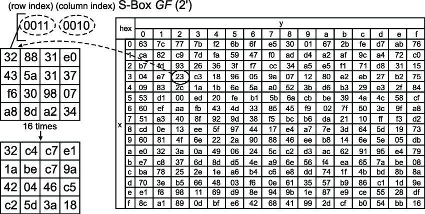
Task 1: Implementation of the S-Box
[!Question] Question In a process named reg, implement the transfer of all states in the s2p_unit in a clocked process with an asynchronous reset. Which process methodology is used in the s2p_unit to implement the proposed functionality?
We just need to assign the value and then get the result. The code that i used:
entity present_sbox is
    port (
        i_data : in  std_ulogic_vector(3 downto 0);
        o_data : out std_ulogic_vector(3 downto 0)
    );
end entity present_sbox;

architecture rtl of present_sbox is
begin
    process(i_data)
    begin
        case i_data is
            when x"0" => o_data <= x"C";
            when x"1" => o_data <= x"5";
            when x"2" => o_data <= x"6";
            when x"3" => o_data <= x"B";
            when x"4" => o_data <= x"9";
            when x"5" => o_data <= x"0";
            when x"6" => o_data <= x"A";
            when x"7" => o_data <= x"D";
            when x"8" => o_data <= x"3";
            when x"9" => o_data <= x"E";
            when x"A" => o_data <= x"F";
            when x"B" => o_data <= x"8";
            when x"C" => o_data <= x"4";
            when x"D" => o_data <= x"7";
            when x"E" => o_data <= x"1";
            when x"F" => o_data <= x"2";
            when others => o_data <= (others => 'X');
        end case;
    end process;
end architecture rtl;
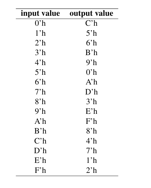
The value is already given, I just implemented as:
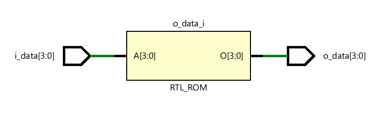
The output of the image can be viewed within the schematic (RTL) as:
Task 2: Implementation of the Substitution Layer
[!Question] Question For the implementation of the substitution layer pre sent_sub_layer, add a design file present_sub_layer.vhdl and copy the testbench file present_sub_layer_tb.vhdl from the shared folder to your Vivado project. Undersources→sim right click on present_sub_layer_tb.vhdl and select Set as Top. Implement present_sub_layer until the testbench tests are performed successfully.
For Substitution layer, we will be working on the input of 64-bit into the 16 groups of 4-bit data (as mentioned in the pdf) Each group passes through its own instance of the S-box from Task 1
entity present_sub_layer is
    port (
        i_data : in  std_ulogic_vector(63 downto 0);
        o_data : out std_ulogic_vector(63 downto 0)
    );
end entity present_sub_layer;

architecture structural of present_sub_layer is
begin
    gen_sboxes : for i in 0 to 15 generate
        sbox_inst : entity work.present_sbox(rtl)
            port map (
                i_data => i_data(4*i + 3 downto 4*i),
                o_data => o_data(4*i + 3 downto 4*i)
            );
    end generate gen_sboxes;
end architecture structural
Check out the work.present_sbox() which extract the mapping of the table and store into 16 separate 4-bit chunks.
Remember, using rtl on Task2, will throws error. The #rtl explicitly tells Vivado to use an architecture named rtl from present_sbox. Above for the s-box code, I used:
architecture behavioral of present_sbox is
So we need to mention the architecture from Task 1, to make a reference to Task2 i.e.
sbox_ins : entity work.present_sbox(behavoiral)
On schematic view from RTL:
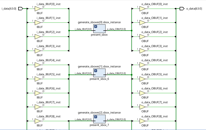
On implementation design, i am getting error for:
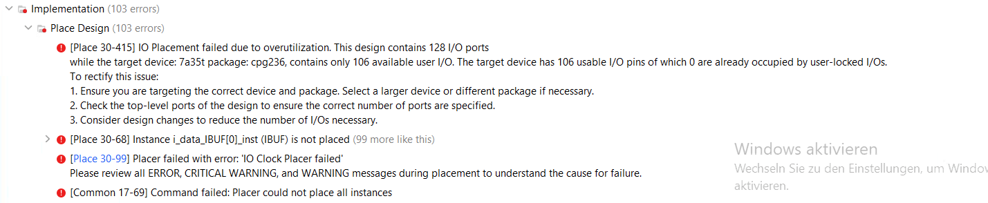
Need to understand that the model of FPGA is very important for the implementation run. As like it mentioned, the FPGA model that i used contain only 128 I/O ports so i need to choose the FPGA greater size for our output.
So, using :

(But, this also throws licensing error)
Try again with:

And this works perfect with our requirements.
And we are given a test benchmark code as:
library ieee;
use ieee.std_logic_1164.all;
use ieee.numeric_std.all;
use ieee.math_real.all;
use std.env.all;

entity sub_layer_tb is
end entity sub_layer_tb;

architecture tb of sub_layer_tb is

constant bit_width              : integer := 64;
constant NUM_INPUTS             : integer := 60;

type stim_array is array (NUM_INPUTS-1 downto 0) of std_ulogic_vector (bit_width-1 downto 0);
signal stimulus : stim_array;

function set_input_array (
    num_inputs : integer;
    bit_width : integer) return stim_array is
    variable generated_array : stim_array;
    variable seed1, seed2: positive;
    variable rand: real;
    variable rand_num: unsigned(bit_width-1 downto 0);
begin

    for i in 0 to num_inputs-1 loop
        for j in 0 to bit_width-1 loop
            uniform(seed1, seed2, rand);
            if rand > 0.5 then
                rand_num(j) := '1';
            else
                rand_num(j) := '0';
            end if;
        end loop;
        generated_array(i) := std_ulogic_vector(rand_num);
    end loop;

    return generated_array;
end function;

function get_present_sbox_output (
    present_sbox_in : std_ulogic_vector(3 downto 0)
    ) return std_ulogic_vector is

        variable present_sbox_out : std_ulogic_vector(3 downto 0);
begin

    case present_sbox_in is
            when x"0" => present_sbox_out := x"C";
            when x"1" => present_sbox_out := x"5";
            when x"2" => present_sbox_out := x"6";
            when x"3" => present_sbox_out := x"B";
            when x"4" => present_sbox_out := x"9";
            when x"5" => present_sbox_out := x"0";
            when x"6" => present_sbox_out := x"A";
            when x"7" => present_sbox_out := x"D";
            when x"8" => present_sbox_out := x"3";
            when x"9" => present_sbox_out := x"E";
            when x"A" => present_sbox_out := x"F";
            when x"B" => present_sbox_out := x"8";
            when x"C" => present_sbox_out := x"4";
            when x"D" => present_sbox_out := x"7";
            when x"E" => present_sbox_out := x"1";
            when x"F" => present_sbox_out := x"2";
            when others => null;
    end case;

    return present_sbox_out;

end function get_present_sbox_output;


component present_sub_layer is
    port(
        i_data: in  std_ulogic_vector(63 downto 0);
        o_data: out std_ulogic_vector(63 downto 0)
    );
end component present_sub_layer;

    signal sub_layer_in              : std_ulogic_vector(bit_width-1 downto 0);
    signal sub_layer_out             : std_ulogic_vector(bit_width-1 downto 0);

begin

    present_sub_layer_inst: present_sub_layer
        port map (
            i_data  => sub_layer_in,
            o_data  => sub_layer_out
        );

    present_sub_layer_test : process

    variable sub_layer_in_val   : std_ulogic_vector (bit_width-1 downto 0);
    variable sub_layer_out_val  : std_ulogic_vector (bit_width-1 downto 0);
    variable num_input_written  : integer;

    begin

        sub_layer_in         <= (others =>'X');

        sub_layer_in_val     := (others => '0');
        sub_layer_out_val    := (others => '0');

        stimulus        <= set_input_array(num_inputs => NUM_INPUTS, bit_width => bit_width);

        wait for 100 ns;

        for i in 0 to NUM_INPUTS-1 loop

            sub_layer_in_val     := stimulus(i);
            sub_layer_in         <= stimulus(i);

            for byte in 0 to 15 loop
                sub_layer_out_val(byte*4+3 downto byte*4) := get_present_sbox_output(sub_layer_in_val(byte*4+3 downto byte*4));
            end loop;

            wait for 20 ns;

            assert sub_layer_out = sub_layer_out_val report "PRESENT Sublayer output wrong! Sublayer Input: " & to_hstring(to_bitvector(sub_layer_in)) & "h" & " | Expected Output: " & to_hstring(to_bitvector(sub_layer_out_val)) & "h" & " | Actual Output: " & to_hstring(to_bitvector(sub_layer_out)) & "h" severity failure;

        end loop;

        sub_layer_in <= (others =>'X');

        wait for 100 ns;

        assert false report "PRESENT Sublayer test passed!" severity note;
        std.env.finish;

    end process present_sub_layer_test;

end architecture tb;
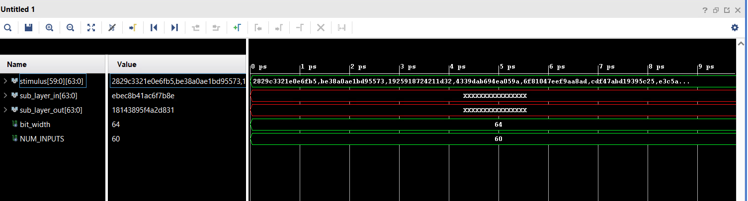
Successfully runs the test benchmark as: