Notiz
Finite State Machines
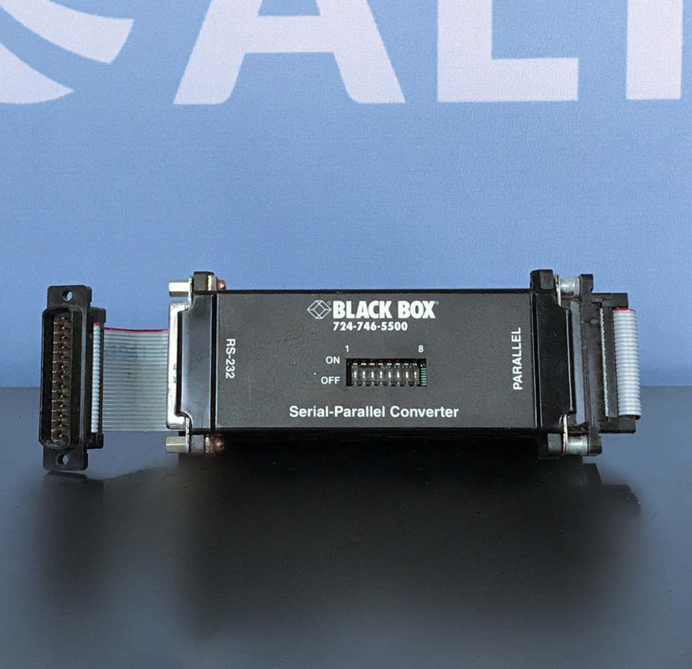
The architecture of a n-bit shift_register is proposed as follows:
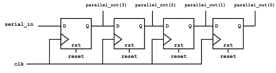
On a rising clock edge, every register takes the output from the previous register and stores the value on its own output. The input register of the shift_register takes the input from the input port. The output port of every register is mapped to the parallel interface output. Here a serial-to-parallel coverter named s2p_unit shall be implemented. The specification of the interface is given as follows:
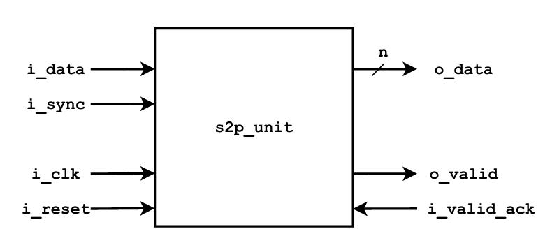
With the s2p_unit, a block of serial data is processed so that it can be read by a parallel interface. After the input i_sync is “1”, the input i_data is shifted into the s2p_unit on a rising clock edge on i_clk. After the number of clock cycles denoted by the bit width of the parallel interface output, the signal o_valid is set to ‘1’ and the output data o_data can be read. Eventually, the parallel transmission is acknowledged with a ‘1’ on the port i_valid_ack and a new serial-to-parallel conversion can be started.
To control the behavior of the s2p_unit, the following state machine is proposed. It consists of the three states IDLE, GET_DATA, and WAIT_ACK. After a reset, the state machine starts in IDLE and waits for input data. All control signals are set to ‘0’. When i_sync is ‘1’ indicating a start of a transmission and the first applied bit at the input i_data, the state machine switches to GET_DATA at the next rising clock edge. The signals cnt_reset and din_en are set to ‘1’. During GET_DATA, only din_en stays ‘1’, all other signals are set to ‘0’. When the signal serial_in_done is ‘1’, the state changes to WAIT_ACK to wait for the parallel interface to read and acknowledge the applied data. The signal dout_en and the output signal o_valid are set to ‘1’, all other signals are set to ‘0’. With i_valid_ack being ‘1’, the transmission is completed and the state machine transitions back to IDLE. The ports of s2p_unit are defined as:
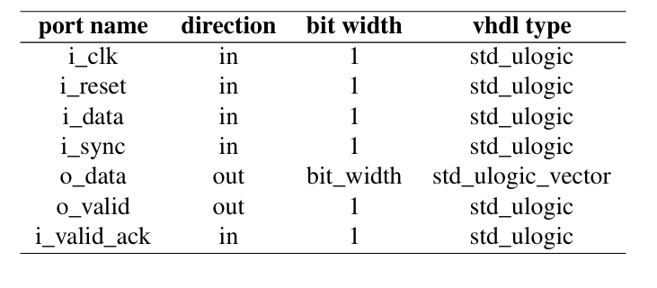
Meaning of those signals:
| Signal | Meaning |
|---|---|
i_clk |
Clock controlling register updates |
i_reset |
Resets the system |
i_data |
One incoming serial bit |
i_sync |
Announces the start of a new transmission |
din_en |
Enables shifting new bits into the register |
cnt_reset |
Resets the bit counter |
serial_in_done |
Indicates the word has been fully received |
dout_en |
Allows the completed word onto o_data |
o_data |
Parallel output word |
o_valid |
Announces that o_data is valid |
i_valid_ack |
Receiver acknowledges the data |
The data width of the parallel output port o_data is configured by bit_width
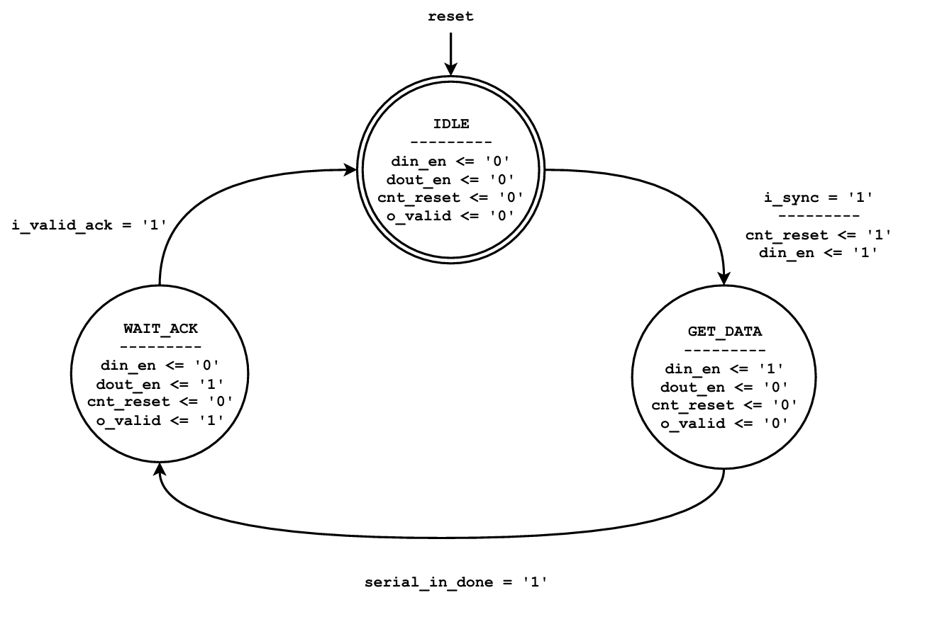
The functionality of control signals are:
- i_sync: when activated, a serial transmission of bit is started. The first bit is present at the input i_data and shifted into the s2p_unit at the next rising clock edge.
- din_en: when activated, the input i_data is shifted into the shift register on a rising clock edge and all other bits are shifted to their next position inside the shift register.
- dout_en: when activated, the bits of the shift register are forwarded to the parallel output port o_data. When inactive, the output signal is set to ‘0’.
- cnt_reset: when activated, the counter values of the bit_counter is reset to $0$ at the next rising clock edge.
- o_valid: denotes if valid data is present at the parallel output port o_data. In WAIT_ACK, the state machine waits for an acknowledgement at the port i_valid_ack that the parallel data is transferred to the requesting unit.
The following functional units are required:
- bit_counter : counts the already shifted serial bits in the shift register. When signal cnt_reset is ’1’, the counter is reset to $0$ on the next rising clock edge, otherwise the bit_counter value is incremented. The signal serial_in_done is set to ’1’ when shifting of all serial bits is completed at the next rising clock edge, so the state machine transitions from GET_DATA to WAIT_ACK.
- shift register : when signal din_en is ’1’, the shifting of the bits on a rising clock edge is activated, otherwise the values of the registers are hold. Note that the LSB of the parallel output data is shifted into the s2p_unit first and the MSB of the parallel output signal is transferred last.
- output data mapping: when all serial bits are shifted into the shift register, the mapping of the shift register bits to the parallel output o_data is activated by the signal dout_en. Otherwise, the output is ’0’.
Need to know: Until now we have implemented counters, shift registers and processes separately. Here, we will combine those ideas to build a Serial-to-Parallel Converter controlled by a Finite State Machine (FSM)
Like previous exercise, all the bits will be passed to another registers. But here only a single bit is sent. but now we have a problem. How does the circuit know when it has received all four bits? And What if the receiving device hasn’t read the result yet? That’s why we have some additional mechanisms:
- Shift Register: stores the data:
- Receives one bit per clock and shifts previously received bits to make room for the new bit.
- Bit Counter - counts the received bits:
- Tracks how many bits have been shifted in. When the configured number has been received, it generates
serial_in_done.
- Tracks how many bits have been shifted in. When the configured number has been received, it generates
- Finite State Machine (FSM) - controls the operation
- Decides when to start collecting bits, when to stop, when to present the completed word, and when another conversion may begin.
==Finite Sate Machine is a digital circuit that has a limited number of states and changes between them based on input conditions==
Now the given sample code is:
library ieee;
use ieee.std_logic_1164.all;
use ieee.numeric_std.all;

entity s2p_unit is

    );
end entity s2p_unit;

architecture rtl of s2p_unit is


begin


	reg : process(-- sensitivity list)
	begin

	end process;


	bit_counter : process(--sensitivity list)
	begin

	end process bit_counter;


	fsm : process(--sensitity list)
	begin

	end process fsm;


	pdata : process (-- sensitivity list)
	begin

	end process pdata;


end architecture rtl;
Task 1: Implementation of Finite State Machine
We need to implement proposed state machine with control signals from s2p_unit.
Before writing the code, we must understand that this FSM must do:
- Understand 3 states. The FSM controls when the serial-to-parallel converter accepts data, presents the completed word, and waits for acknowledgement.
| State | din_en |
dout_en |
cnt_reset |
o_valid |
|---|---|---|---|---|
IDLE |
0 | 0 | 0 | 0 |
GET_DATA |
1 | 0 | 0 | 0 |
WAIT_ACK |
0 | 1 | 0 | 1 |
There is one special case: when i_sync= 1 in IDLE, the FSM must assert cnt_resetand din_ento prepare for the first incoming bit.
- Understand the state Transition
The logic is:
- In
IDLE, wait fori_sync = '1' - In
GET_DATA, keep receiving bits untilserial_in_done = '1' - In
WAIT_ACK, present the parallel output and wait fori_valid_ack='1' - After the acknowledgement, return to IDLE
- In
Now the code is:
fsm : process(all)
begin
    -- Default control signals
    din_en    <= '0';
    dout_en   <= '0';
    cnt_reset <= '0';
    o_valid   <= '0';

    -- Stay in the current state by default
    next_state <= current_state;

    case current_state is

        when IDLE =>
            if i_sync = '1' then
                cnt_reset  <= '1';
                din_en     <= '1';
                next_state <= GET_DATA;
            end if;

        when GET_DATA =>
            din_en <= '1';

            if serial_in_done = '1' then
                next_state <= WAIT_ACK;
            end if;

        when WAIT_ACK =>
            dout_en <= '1';
            o_valid <= '1';

            if i_valid_ack = '1' then
                next_state <= IDLE;
            end if;

    end case;
end process fsm;
This is implemented same as that of figure. There are two types of FSM:
- Moore FSM
- Outputs depend only on the current state.
- Outputs generally change when the state changes.
- Mealy FSM
- Outputs depend on the current state and inputs
- Output can change when inputs change.
The above implementation FSM is Mealy FSM, because its control outputs depend on both the current state and an external input.
For example:
when IDLE =>
    if i_sync = '1' then
        cnt_reset <= '1';
        din_en    <= '1';
    end if;
Even though the FSM is still in IDLE, changing i_sync from 0 to 1 can immediately change din_en and cnt_reset.
That is characteristic of a Mealy FSM.
Task 2: Implementation of Shift Register and Output Mapping:
[!Question] Question In the process named pdata, implement the described control of the shift register and the output mapping. Keep care of the shift order inside the shift register. What kind of implementation methodology is used here to implement the shift register?
So we need to implement two things inside pdata process:
- Shift register : Collect serial bits when
din_en = '1' - Output mapping: Forward the collected bits to o_data when dout_en = ‘1’
Need of din_en ?
- In Exercise 3, our shift register shifted at every rising clock edge. But here, shifting should happen only while the converter is receiving data.
Example:
  if din_en = '1' then
  -- Shift one bit
  end if;
If
din_en=0the register must hold its existing value.
pdata : process(data_reg, i_data, din_en, dout_en)
    variable temp : std_ulogic_vector(bit_width - 1 downto 0);
begin
    -- Preserve the current contents by default
    temp := data_reg;

    if din_en = '1' then
        temp := i_data & data_reg(bit_width - 1 downto 1);
    end if;

    next_data_reg <= temp;

    if dout_en = '1' then
        o_data <= data_reg;
    else
        o_data <= (others => '0');
    end if;
end process pdata;
Task 3: Implementation of Bit Counter
[!Question] Question In a process named bit_counter, implement the bit_counter for counting the already shifted serial bits. Keep care of resetting the counter on the next rising clock edge when cnt_reset is active and activating serial_in_done when all serial bits are shifted into the shift register on the next rising clock edge.
bit_counter determines how many serial bits have been received and when reception is complete.
bit_counter : process(count_reg, cnt_reset, din_en)
begin
    next_count_reg <= count_reg;
    serial_in_done <= '0';

    if cnt_reset = '1' then
        next_count_reg <= 0;

    elsif din_en = '1' then
        if count_reg = bit_width - 2 then
            next_count_reg <= count_reg + 1;
            serial_in_done <= '1';
        else
            next_count_reg <= count_reg + 1;
        end if;
    end if;
end process bit_counter;
This example uses a particular counting convention: the first bit is captured while the counter resets to zero, and the remaining bits are counted from there. It assumes bit_width >= 2
But why ?
Lets understand with and example: if bit_width = $5$
We want to receive 5 bits:
| Rising Edge | Action | Counter After edge |
|---|---|---|
| 1 | First bit captured; counter reset | 0 |
| 2 | Second bit captured | 1 |
| 3 | Third bit captured | 2 |
| 4 | Fourth bit captured | 3 |
| 5 | Fifth bit captured | 4 |
Task 4: Implementation of Register Transfer
[!Question] Question In a process named reg, implement the transfer of all states in the s2p_unit in a clocked process with an asynchronous reset. Which process methodology is used in the s2p_unit to implement the proposed functionality?
This is the part that connects everything you have implemented.
In Exercise 3, Task 3, where we used two processes:
- A combinational process calculated the next values.
- A clocked process stored those values.
What are we storing? There are three important pieces of stored information:
current_state- Remembers whether the FSM is inIDLE,GET_DATA, orWAIT_ACKdata_reg- Remembers the serial bits already collectedcount_reg- Remembers the counter value
reg : process(i_clk, i_reset)
begin
    if i_reset = '1' then

        current_state <= IDLE;
        data_reg      <= (others => '0');
        count_reg     <= 0;

    elsif rising_edge(i_clk) then

        current_state <= next_state;
        data_reg      <= next_data_reg;
        count_reg     <= next_count_reg;

    end if;
end process reg;
The reset is outside the rising_edge:
First see:
if i_reset = '1' then
    ...
elsif rising_edge(i_clk) then
    ...
end if;
This describes an asynchronous reset.
That means asserting i_reset resets the registers without waiting for a rising clock edge.
So need to understand:
| Synchronous Reset | Asynchronous Reset |
|---|---|
Reset checked inside rising_edge |
Reset checked before rising_edge |
| Requires a clock edge | Does not require a clock edge |
| Used in your previous shift-register exercise | Required for Task 4 |
This is a separated combinational and sequential implementation, commonly described as a two-process methodology when the combinational logic is grouped into one process.
One complete conversion works like this:
The FSM waits in IDLE, i_sync starts reception, the shift register collects the bits, the counter detects completion, the FSM enters WAIT_ACK, and the parallel output remains available until i_valid_ack arrives.
This exercise extends that same principle.