Notiz
Assignments and Processes
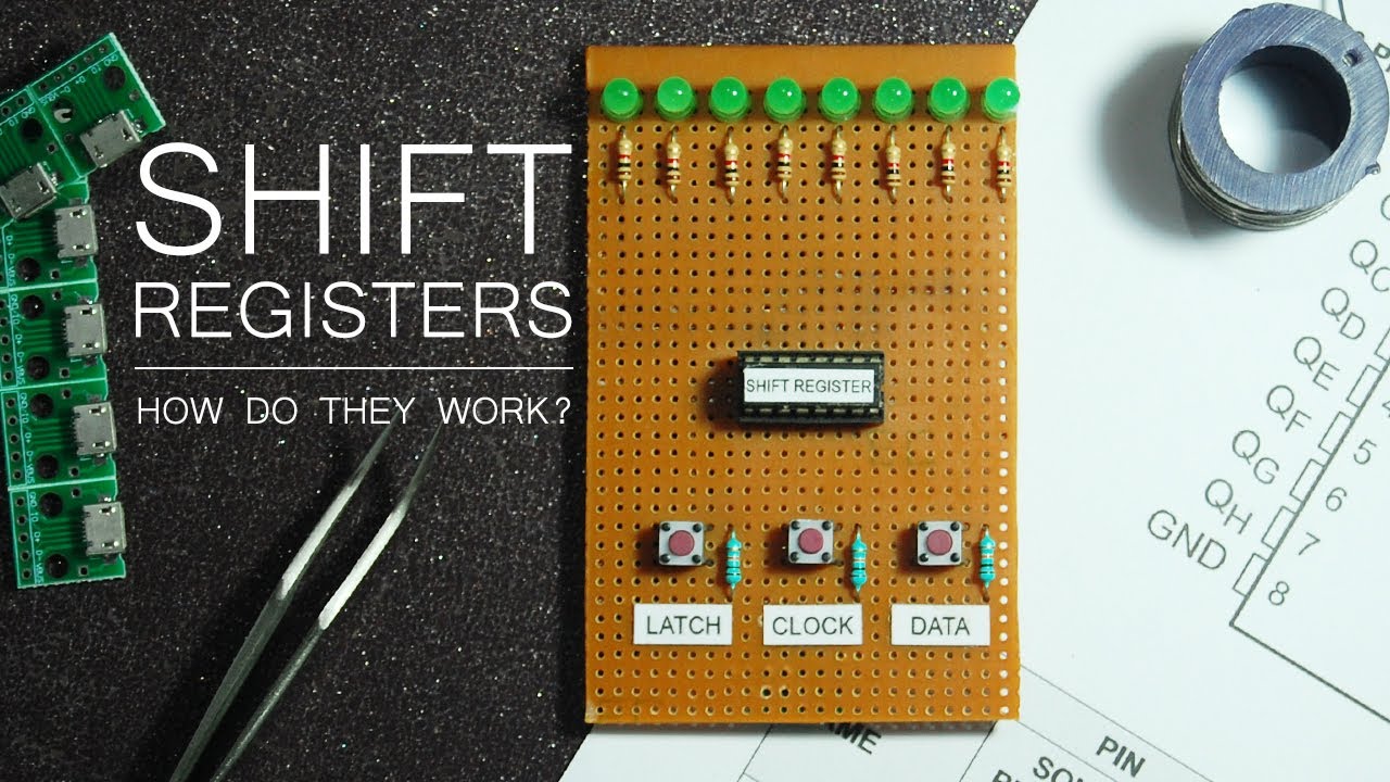
The architecture of a n-bit shift_register is proposed as follows:
==🟢In previous exercise, we learned how to calculate a new value using an adder and store it using a clock==
==In this exercise we will learn how to move data through multiple registers using clock signals, and how different VHDL assignment styles affect that behavior==
In this exercise, ==🟣On a rising clock edge, every register takes the output from the previous register and stores the value on its own output==. The input register of the shft_register takes the input from the input port and the output register stores its output at the output ports of the shift_register accordingly.
The ports are specified as:
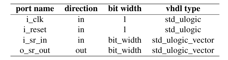
bit_width is the data width of the input and output port.
The template before implementing the tasks is:
library ieee;
use ieee.std_logic_1164.all;
use ieee.numeric_std.all;

entity shift_register is

end entity shift_register;

------------------------------------------------------------------
---------- Signal-based Shift-Register Implementation ------------
------------------------------------------------------------------

architecture signal_implementation of shift_register is

begin

end architecture signal_implementation;

------------------------------------------------------------------
---------- Variable-based Shift-Register Implementation ----------
------------------------------------------------------------------

architecture variable_implementation of shift_register is

begin

end architecture variable_implementation;

-------------------------------------------------------------------
-- Two-Process-Methodology-based Shift-Register Implementation ----
-------------------------------------------------------------------

architecture two_process_implementation of shift_register is

begin

end architecture two_process_implementation;
Task 1: Shift Register with Signal Assignments
For the signal based implementation of the shift register, use a one-process methodology only with signal assignments for the implementation of each register in the shift_register. For this, use the proposed architecture signal_implementation inside the shift_register entity.
entity shift_register is
    generic (
        bit_width : positive := 4
    );
    port (
        i_clk    : in  std_ulogic;
        i_reset  : in  std_ulogic;
        i_sr_in  : in  std_ulogic_vector(bit_width - 1 downto 0);
        o_sr_out : out std_ulogic_vector(bit_width - 1 downto 0);
    );
end entity shift_register;


architecture signal_implementation of shift_register is

	signal reg_0 : std_ulogic_vector(bit_width - 1 downto 0);
	signal reg_1 : std_ulogic_vector(bit_width - 1 downto 0);
	signal reg_2 : std_ulogic_vector(bit_width - 1 downto 0);
	signal reg_3 : std_ulogic_vector(bit_width - 1 downto 0);

begin

    process(i_clk)
    begin
        if rising_edge(i_clk) then
            if i_reset = '1' then
                reg_0 <= (others => '0');
                reg_1 <= (others => '0');
                reg_2 <= (others => '0');
                reg_3<= (others => '0');
            else
                reg_0 <= i_sr_in;
                reg_1 <= reg_0;
                reg_2 <= reg_1;
                reg_3 <= reg_2;
            end if;
        end if;
    end process;

    o_sr_out <= reg_3;
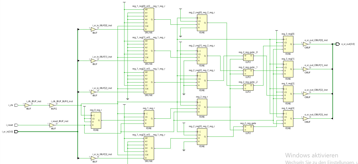
Task 2: Shift Register with Variable Assignments
For variable-based implementation of shift register, use a one-process methodology with variable assignments for the implementation of each register in the shift_register entity.
architecture variable_implementation of shift_register is
begin
process(i_clk)
	variable reg_0 : std_ulogic_vector(bit_width - 1 downto 0);
	variable reg_1 : std_ulogic_vector(bit_width - 1 downto 0);
	variable reg_2 : std_ulogic_vector(bit_width - 1 downto 0);
	variable reg_3 : std_ulogic_vector(bit_width - 1 downto 0);

begin
if rising_edge(i_clk) then
	if i_reset = '1' then
		reg_0 := (others => '0');
		reg_1 := (others => '0');
		reg_2 := (others => '0');
		reg_3 := (others => '0');

	else
		reg_3 := reg_2;
		reg_2 := reg_1;
		reg_1 := reg_0;
		reg_0 := i_sr_in;
	end if;
	o_sr_out <= reg_3;
end if;
end process;
end architecture variable_implementation
As like in Task-1, we didn’t assign the values for registers, because variables work differently. Example:
if i_sr_in = 1011, all four variables can become 1011 during the same clock-edge execution. So the solution is:
Reverse the assignment order i.e we update the last stage first.
Task 3: Shift Register with a Two Process Methodology
For the two-process-based implementation of the shift register, separate the transition of a register from its input generation using two dedicated processes. For this, use the proposed architecture two_process_implementation inside the shift_register entity.
architecture two_process_implementation of shift_register is

signal reg_0, reg_1, reg_2, reg_3: std_ulogic_vector(bit_width - 1 downto 0);

signal next_0, next_1, next_2, next_3: std_ulogic_vector(bit_width - 1 downto 0);

begin
---Process 1: Generate the next values:```
    process(all)
    begin
        next_reg_0 <= i_sr_in;
        next_reg_1 <= reg_0;
        next_reg_2 <= reg_1;
        next_reg_3 <= reg_2;
    end process;

---Process 2: Update the registers on rising clock edges
process(i_clk)
begin
if rising_edge(i_clk) then
    if i_reset = '1' then
        reg_0 <= (others => '0');
        reg_1 <= (others => '0');
        reg_2 <= (others => '0');
        reg_3 <= (others => '0');
    else
        reg_0 <= next_reg_0;
        reg_1 <= next_reg_1;
        reg_2 <= next_reg_2;
        reg_3 <= next_reg_3;
   end if;
 end if;
end process;
o_sr_out <= reg_3;


end architecture two_process_implementation;
The purpose of this task is, how to separate the logic that calculates the next value from the registers that store that value. In both task1 and task2, we used only one process to transfer the values from one register to another. But here:
- Process 1 decide what each register should receive next
- Notice, there is not
rising_edge(i_clk). This process is not waiting for a clock. It calculates the next register values whenever one of its inputs changes. - But the actual register have not changed yet.
- Notice, there is not
- Process 2 Store the prepared values when the clock rises
The important thing is that, these two processes are concurrent, not sequential software steps. Process 1 continuously responds to changes. Process 2 updates the stores state only on rising clock edges.
The tb file is:
library ieee;
use ieee.std_logic_1164.all;
use ieee.numeric_std.all;
use ieee.math_real.all;
use std.env.all;

entity shift_reg_tb is
end entity shift_reg_tb;

architecture tb of shift_reg_tb is

constant bit_width              : integer := 5;
constant NUM_INPUTS             : integer := 10;

component shift_register is
    generic (
        bit_width : integer
    );
    port (
        i_clk           : in    std_ulogic;
        i_reset         : in    std_ulogic;
        i_sr_in         : in    std_ulogic_vector(bit_width-1 downto 0);
        o_sr_out        : out   std_ulogic_vector(bit_width-1 downto 0)
    );
end component shift_register;

    type stim_array is array (NUM_INPUTS-1 downto 0) of std_ulogic_vector (bit_width-1 downto 0);
    signal stimulus : stim_array;

    signal sr_in_sig                            : std_ulogic_vector(bit_width-1 downto 0);
    signal sr_out_signal_implementation         : std_ulogic_vector(bit_width-1 downto 0);
    signal sr_out_variable_implementation       : std_ulogic_vector(bit_width-1 downto 0);
    signal sr_out_two_process_implementation    : std_ulogic_vector(bit_width-1 downto 0);

    signal clk_sig      : std_ulogic := '1';
    signal reset_sig    : std_ulogic;

    function set_input_array (
        num_inputs : integer;
        bit_width : integer) return stim_array is
        variable generated_array : stim_array;
        variable seed1, seed2: positive;
        variable rand: real;
        variable int_rand: integer;
    begin

        for i in 0 to num_inputs-1 loop
            uniform(seed1, seed2, rand);
            int_rand := integer(trunc(rand*(2**bit_width)));
            generated_array(i) := std_ulogic_vector(to_unsigned(int_rand, bit_width));
        end loop;

        return generated_array;
    end function;

    constant CLOCK_SHIFTS : integer := 4;

begin

    shift_reg_signal: entity work.shift_register(signal_implementation)
        generic map (
            bit_width => bit_width
        )
        port map (
            i_clk       => clk_sig,
            i_reset     => reset_sig,
            i_sr_in     => sr_in_sig,
            o_sr_out    => sr_out_signal_implementation
        );

    shift_reg_variable: entity work.shift_register(variable_implementation)
        generic map (
            bit_width => bit_width
        )
        port map (
            i_clk       => clk_sig,
            i_reset     => reset_sig,
            i_sr_in     => sr_in_sig,
            o_sr_out    => sr_out_variable_implementation
        );
    shift_reg_two_process: entity work.shift_register(two_process_implementation)
        generic map (
            bit_width => bit_width
        )
        port map (
            i_clk       => clk_sig,
            i_reset     => reset_sig,
            i_sr_in     => sr_in_sig,
            o_sr_out    => sr_out_two_process_implementation
        );

    clock_generator : process (clk_sig)
    begin
            clk_sig <= not clk_sig after 10 ns;
    end process clock_generator;

    counter_test : process
        variable num_input_written : integer;
        variable num_input_readed : integer;
        variable clock_shift_count : integer;
    begin

        reset_sig <= '1';

        wait for 100 ns;

        reset_sig <= '0';

        stimulus <= set_input_array(num_inputs => NUM_INPUTS, bit_width => bit_width);
        num_input_written := 0;
        num_input_readed := 0;
        clock_shift_count := 0;

        test_cases: loop

            wait until falling_edge (clk_sig);

            if clock_shift_count = CLOCK_SHIFTS then
                assert sr_out_signal_implementation = stimulus(num_input_readed) report "Shift Register output of Signal Implementation not correct! Received Output: " & integer'image(to_integer(unsigned(sr_out_signal_implementation))) & " Expected Output: " & integer'image(to_integer(unsigned(stimulus(num_input_readed)))) severity failure;
                assert sr_out_variable_implementation = stimulus(num_input_readed) report "Shift Register output of Variable Implementation not correct! Received Output: " & integer'image(to_integer(unsigned(sr_out_variable_implementation))) & " Expected Output: " & integer'image(to_integer(unsigned(stimulus(num_input_readed)))) severity failure;
                assert sr_out_two_process_implementation = stimulus(num_input_readed) report "Shift Register output of Two Process Implementation not correct! Received Output: " & integer'image(to_integer(unsigned(sr_out_two_process_implementation))) & " Expected Output: " & integer'image(to_integer(unsigned(stimulus(num_input_readed)))) severity failure;

                num_input_readed := num_input_readed + 1;
            else
                clock_shift_count := clock_shift_count + 1;
            end if;

            exit test_cases when num_input_readed = NUM_INPUTS;

            if num_input_written < NUM_INPUTS then
                sr_in_sig <= stimulus(num_input_written);
                num_input_written := num_input_written + 1;
            else
                sr_in_sig <= (others => '0');
            end if;

        end loop;

        reset_sig <= '1';

        wait for 100 ns;

        assert false report "Test: Shift register test passed!" severity note;
        std.env.finish;

    end process counter_test;

end architecture tb;
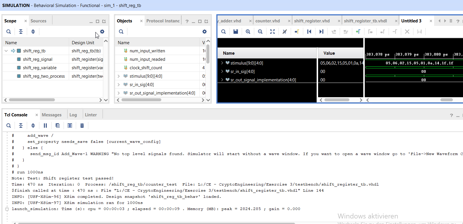
Testbench: