Notiz
Hierarchy and States

We will build ripple_carry_adder with existing full_adder. The architecture of 4-bit ripple_carry_adder is proposed as:
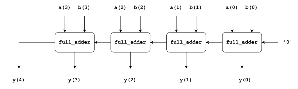
It takes 4-bit inputs $a$ and $b$ and produces $5-bit$ output $y$. In every bit stage, the sum output of a full_adder corresponds to the output of the ripple_carry_adder. In the MSB stage, the carry output of the corresponding full_adder is the MSB of the output of the ripple_carry_adder. The carry input of the full_adder at the LSB stage of the ripple_carry_adder is set to ‘0’. For all other bit stages, the carry output of a former stage serves as the carry input of the following stages.
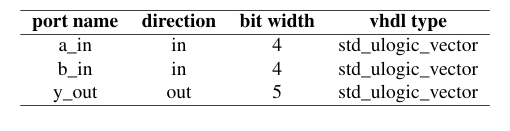
Ports of the ripple_carry_adder is specified as:
entity ripple_carry_adder is
    port (
        a_in  : in  std_ulogic_vector(3 downto 0);
        b_in  : in  std_ulogic_vector(3 downto 0);
        y_out : out std_ulogic_vector(4 downto 0)
    );
end entity ripple_carry_adder;

architecture structural of ripple_carry_adder is
    signal carry : std_ulogic_vector(4 downto 0);
begin
    carry(0) <= '0';

    fa0 : entity work.full_adder
        port map (
            a_in      => a_in(0),
            b_in      => b_in(0),
            carry_in  => carry(0),
            sum_out   => y_out(0),
            carry_out => carry(1)
        );

    fa1 : entity work.full_adder
        port map (
            a_in      => a_in(1),
            b_in      => b_in(1),
            carry_in  => carry(1),
            sum_out   => y_out(1),
            carry_out => carry(2)
        );

    fa2 : entity work.full_adder
        port map (
            a_in      => a_in(2),
            b_in      => b_in(2),
            carry_in  => carry(2),
            sum_out   => y_out(2),
            carry_out => carry(3)
        );

    fa3 : entity work.full_adder
        port map (
            a_in      => a_in(3),
            b_in      => b_in(3),
            carry_in  => carry(3),
            sum_out   => y_out(3),
            carry_out => carry(4)
        );

    y_out(4) <= carry(4);
end architecture structural;
The carry from the first stage propagates to the second, then the third, then the fourth. This propagation takes a small amount of physical time, which is why the circuit is called a ripple carry adder.
Task 2: Implementation and Testing of Generic Ripple Carry Adder:
We here will adapt the bit-width of proposed ripple_carry_adder to a specific system instead of writing code for every bit (fa0, fa1….). The ports for the generic ripple_carry_adder is:
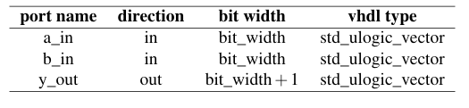
So we will be using bit width as bit_width parameter in vhdl.
entity ripple_carry_adder is
--  Port ( );
generic (
          bit_width : positive := 4
      );
      port (
          a_in  : in  std_ulogic_vector(bit_width - 1 downto 0);
          b_in  : in  std_ulogic_vector(bit_width - 1 downto 0);
          y_out : out std_ulogic_vector(bit_width downto 0)
      );
end ripple_carry_adder;

architecture Behavioral of ripple_carry_adder is
    component full_adder is
        port (
            a_in : in std_ulogic;
            b_in : in std_ulogic;
            carry_in: in std_ulogic;
            sum_out: out std_ulogic ;
            carry_out: out std_ulogic
            );
     end component;
     signal carry : std_ulogic_vector (bit_width downto 0);


begin
    carry (0) <= '0' ;

    gen_adders : for i in 0 to bit_width - 1 generate
        fai : full_adder
            port map(
                a_in => a_in(i),
                b_in => b_in(i),
                carry_in => carry(i),
                sum_out => y_out(i),
                carry_out => carry(i+1)
                );
     end generate;

     y_out(bit_width) <= carry(bit_width);


end Behavioral;
Task 3: Implementation and Testing of a Parametric n-bit Counter
[!Question] Question The following specification represents a n-bit parametric counter, which increments its value by $1$ at every single rising edge of a clock cycle from the clock input port i_clk. To start the counter from zero, a synchronous active high reset at port i_reset for at least one clock cycle is needed. The maximum value of the counter output o_counter_value is the maximum value that can be represented with the number of bits set by the parameter bit_width.
The ports of the parametric counter are specified as follows:
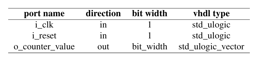
When the maximum value of the counter is reached, the counting shall start again with the value zero.
We will be using previously implemented parametric ripple_carry_adder for the implementation of the counter and take care of the generic bit width of our design.
entity counter is
--  Port ( );
    generic (
          bit_width : positive := 4
      );
      port (
          i_clk           : in  std_ulogic;
          i_reset         : in  std_ulogic;
          o_counter_value : out std_ulogic_vector(bit_width - 1 downto 0)
      );
end counter;

architecture Behavioral of counter is
component ripple_carry_adder is
          generic (
              bit_width : positive := 4
          );
          port (
              a_in  : in  std_ulogic_vector(bit_width - 1 downto 0);
              b_in  : in  std_ulogic_vector(bit_width - 1 downto 0);
              y_out : out std_ulogic_vector(bit_width downto 0)
          );
end component;

signal counter_reg : std_ulogic_vector(bit_width - 1 downto 0);
signal add_result  : std_ulogic_vector(bit_width downto 0);
signal one_vector  : std_ulogic_vector(bit_width - 1 downto 0);

begin
one_vector <= (0 => '1', others => '0');

      adder_inst : ripple_carry_adder
          generic map (
              bit_width => bit_width
          )
          port map (
              a_in  => counter_reg,
              b_in  => one_vector,
              y_out => add_result
          );

      process(i_clk)
      begin
          if rising_edge(i_clk) then
              if i_reset = '1' then
                  counter_reg <= (others => '0');
              else
                  counter_reg <= add_result(bit_width - 1 downto 0);
              end if;
          end if;
      end process;

      o_counter_value <= counter_reg;

end Behavioral;
==The register only stores the new value on a rising clock edge==
rising_clock(i_clk)checks for a transition from $0$ to $1$, not simply whether the clock is 1. And the counter will increases only when the clock changes from 0 to 1.
Remember:
i_clktells the counter when to updatei_resettells the counter whether to clear its value to zero.counter_regstores the current count.
Just remember, we are just implementing the full_adder using counter so it wont be giving the result same as task 2, because we are just using bit 4 for this task and this task will increment the value until 15 only.
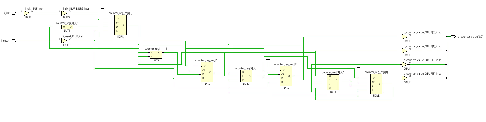
The schematic diagram is: