Notiz
Filesystem Analysis
Firstly we need to know that data is stored in digital form of series of 1’s and 0’s
But it must be understandable by humans so it must be organized within a organization system.
We can think of organizing files, like how books are organized in the library.
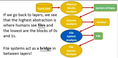
A system similar to the ones used at libraries is what we call in the computer’s world a “file system”; This means we could think of a file system, as the method used to track files on a disk or partition.
When we acquire a forensic image, we usually do at the device layer; this means that it will contain files and whatever inside them along with the file system’s metadata itself.
Analyzing file systems is one of the most important task a digital forensics investigator must be capable of doing.
To analyze file system, we must need to understand how file systems work, and know how to interpret those blocks of 0’s and 1’s into file system metadata. These metadata could help lead to the actual data found in files required for the investigation.
Also the deleted data too. 🤔
Question is :How can we acquire deleted data ?
Truth is, when we delete a file, the pointer that is pointing or tracking that file is removed and no longer there.
Another question is: What about the data?
And yes it will stay there. It will stay as long as the location where it is stored has not been used again by another file.
It’s not easy to perform analysis during such situation. We face couple of challenges:
- First we need to understand how the data is stored on disk (We done in previous module)
-
Secondly, we need to understand how to interpret such data into useful file system information and/or files.
a. Directories are actually a specific type of file (to be continued in upcoming slides)
b. And to do that, we first need to understand how file systems organize files on storage media.
And all those files and directories we see are actually just an arbitrarily sequence of bytes (0’s and 1’s) that are stored within some media (eg: disks)
Also we read in previous module that disks are capable of reading and writing using blocks of sectors. By d way, sectors have fixed size.
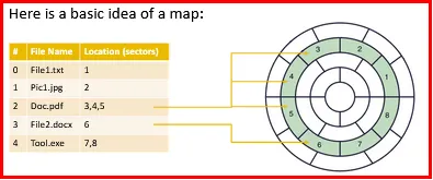
Now the question is: Then how can we know that which sequence of bytes belong to which sectors and which sectors, belong to which file?
Hence, we need a map or something like that.
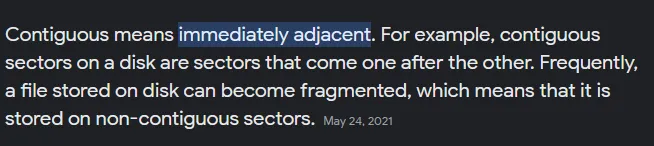
And this lead to another query; whether files will actually reserve contiguous sectors or could files actually reserve and allocate any free (unallocated) sector they want?
And understand (Free means the sector is unallocated and unfree means the sector is allocated)
The allocation idea actually means: we need a map and an algorithm or technique to select the free sectors found on the disk and allocate them on files.
The allocation algorithm or technique for file system will vary with other as they choose based on what they find better.
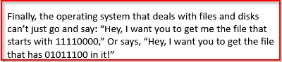
We need a mechanism to achieve this and this is where file names jumps in.
At last, We basically need the following:
- Names to label files
- A map capable of tracking:
- Names to files
- Files to sectors
- Sectors to the 0s and 1s on storage media (eg: disks)
FAT File System Analysis:
FAT (File Allocation Table) is a very simple, yet robust computer file system. It was originally designed to be used by floppy disks in 1977. FAT is one of the oldest file systems used by Microsoft with their MS-DOS operating system.
FAT uses simple index table to track files on disks, that’s why it is called File Allocation Table.
It has not been disappeared; it is still the default file system used today by USB thumb drive and Memory Card used with Cameras.
We will also find it used on EFI booting partitions.
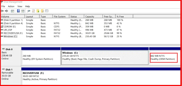
Unified Extensible Firmware Interface, it’s purpose is to store all data about device initialization and startup in a .efi file, which is kept on special disk partition called EFI System Partition (ESP). ESP also holds the bootloader responsible for booting the operating system.
(GPT partition used UEFI partition)

FAT file system has different types:
- FAT12
- FAT16
- FAT32
- Extended File Allocation Table (ExFAT)
(FAT12, FAT16, FAT32) → For this course
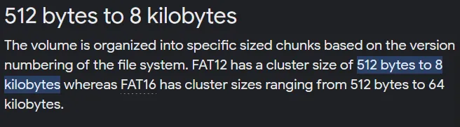
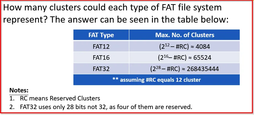
What about those numbers in FAT system (12, 16,32)?
These refers to number of bits used for clusters addressing. That means a 12-bit FAT can have a cluster size of 2^12 (different numbers, Ex: compare with hex as hex contain 2^16 diff numbers) [Higher the number (bits), higher will be the size. For ex, if 3-bits, it will have 8 (2^3) different numbers as; 000, 001, 010, 011, 100,101,111; Also , size = 8 bits = 1bytes)
Similarly, for 12-bit FAT; It will have 2^12 different numbers or 2^12 bits size = 4096 bits ⇒ 512 bytes (4096/8)
Again our question rise as, What actually is cluster here?
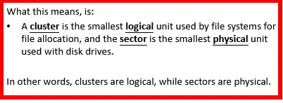
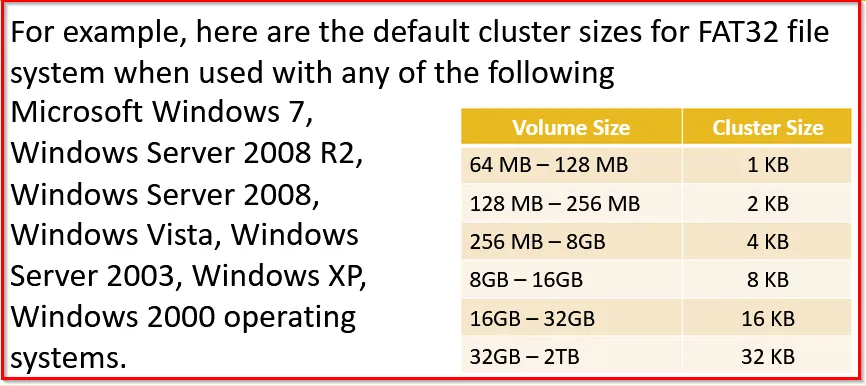
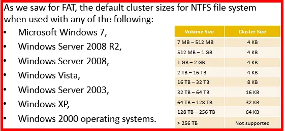
A cluster, is the smallest logical unit a file system can allocate to a file. The cluster size is defined at the time you initialize the partition or volume; That means, it is defined when we format the partition.
A cluster can be anything from 512 bytes, up to the limit of the file system used.
The reason for cluster being the minimal size of 512-bytes is , the minimum size of sector is 512-bytes.
The number of sectors per cluster is defined when we format the disk and it is determined by default based on the size of disk or partition used.
This number is defined within the Boot Record of the file system.
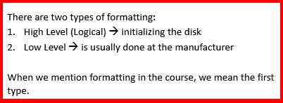
Formatting the disk is a way of preparing the disk to hold data on it. The format initializes the file system and the data structures required to track files on the disk.
Whenever a file is created, the file system must allocate a number of clusters to it. This is where the number of sectors per cluster is important because the cluster’s size has an impact on both the performance and utilization of disk
Using a big cluster might lead to waste in disk capacity and using a small cluster could lead to an overhead
[Also we need to understand that when we say a cluster could represent a number of sectors, this means they are contiguous. That means; these sectors follows each other, they are one after the other]
For example: if we have 4 sectors for a cluster, then whenever we create a file, it will be allocated four contiguously allocated sectors. This helps file systems access data easily.
The main reason is: The access speed for a file will be faster. For Example: if we have a Hard Disk drive, then disk will not need to move up and down for the platters and heads. It only needs to know where the first sector for the file resides and the slide through the sector for that file.
[Note: If the file is too large to fit within a track or platter, then the head will have to move to that location for accessing such file.]
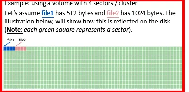
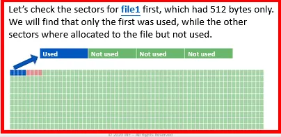
In this example it is assumed that there were no files previously created on the disk and we created file1 and file2 after each other. Understand that we will not always see in such way. It’s just an ex:
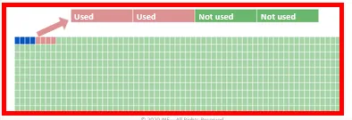
Now check for file2, which has 1024 bytes. We will find only two sectors were used, while other two were allocated to the file but not used.
Here we need to understand that, at High-Level view of the disk, we found that first four sectors were allocated to file1 and the next four sectors were for file2, but when we checked a Low-level view of the content for each cluster, we found that file1 had a whole cluster allocated but used only one sector of the cluster, while file2 had used only half the sectors of the cluster.
It means, file1 wasted three sectors while file2 wasted only two.
Structures:
Let’s view the structures of the FAT file system. The figure below shows the high-level view of the FAT file system structure within the disk.

-
Reserved Area:
The size of sectors within the Reserved Area depends on the type of FAT file system used:
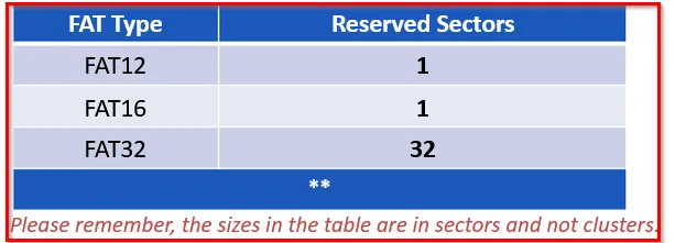
-
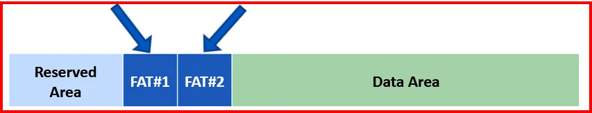
FAT Area:
FAT Area for FAT32 file system has two parts whereas for FAT12 and FAT16 have one one.
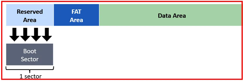
As the Reserved Area depends on the FAT used, let’s check for the FAT12/16 file system.
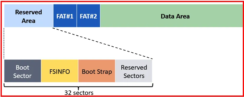
As for the FAT32 file system, the structure is :
Let’s view the boot sector of FAT32 volume using Disk Editor:
When we check for the 32 sectors allocated:
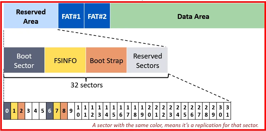
From the above diagram we can assume that:
→ Sector 0 and 6 are used for the Volume Boot Sector
→ Sectors 1 and 7 are used for the File System Information (FSINFO) structure.
→ Sectors 2 and 8 are used for the Bootstrap Code.
Boot strap sectors will be empty if the volume is non-bootable, but it still end with a signature (0x55AA).Boot Sector:
Let’s first view the boot sector for FAT12/16:
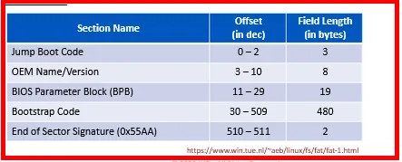
Note: The size of BIOS Parameter Block (BPB), Extended BIOS Parameter Block (EBPB) and the Bootstrap code varies based on the operating system and versions.
The boot sector for the FAT32 file system:
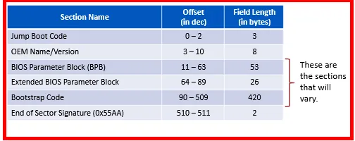
→ OEM - Original Equipment Manufacturer (It is used for system recovery or factory restore. It allows users to easily and quickly restore the system to original state when system failure or system crash occurs.)
→ BIOS Parameter Block - It is a data structure in Volume Boot Record (VBR) describing the physical layout of data storage volume. On partitioned devices, such as Hard Disks, it describes the volume partition and for unpartitioned devices (like Floppy Disks, it describes entire medium)
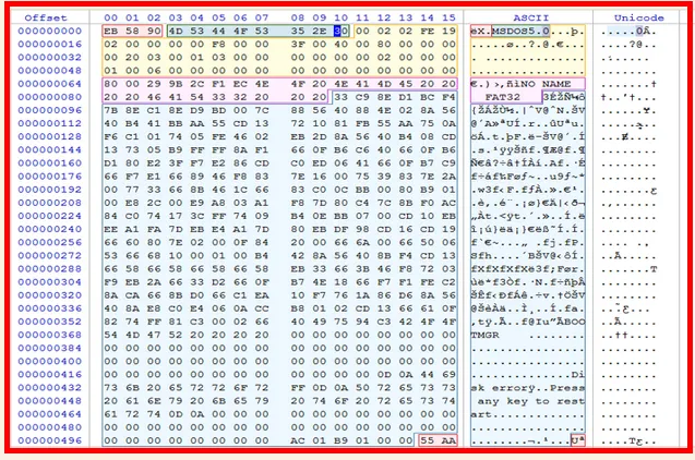
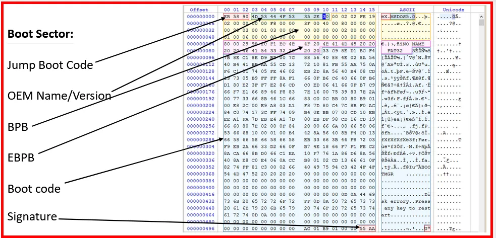
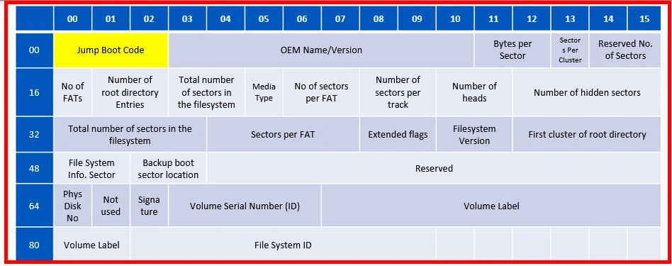
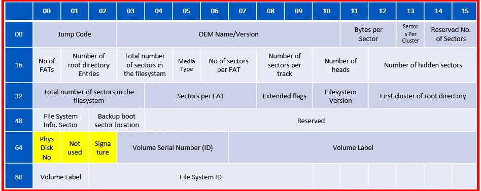
Byte Level dissection of the Boot Sector of a FAT32 file system.
→ Jump Boot Code holds the command used to jump to the boot code.
→ In the above example it shows, EB 58 90
→ EB 58 is the byte code for the assemble instruction jmp 005A.
→ 90 is the byte code for the assemble instruction NOP {mnemonic for NO Operation}
→ OEM Name/Version could hold the type of system the disk was formatted for, or the utility used or even a serial no. In above example; it holds MSDOS5.0 (From ASCII table)
BIOS Parameter Block (BPB):
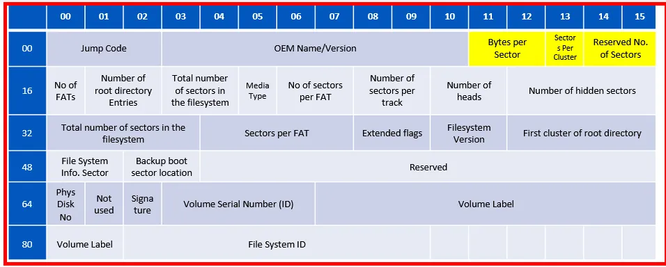
- Bytes Per Sector: We here have a value of 0002 that equals to 512 bytes/sector
- Sectors per Cluster: We here have two sectors per cluster, based on the value found (From Fig). It means (512+512 bytes of 1 cluster)
-
Reserved No of sectors: Holds the number of reserved sectors. It is variable in a FAT32 file system. From above fig: we see that the value of FE19 equals 6654 sectors.
→ How is this calculation done?
So first the value we obtained within the Disk Editor is converted to little-endian method, which means FE19→ 19FE, Now convert into decimal we get: 6654 sectors - No. of FATs: holds number of FAT tables. From above fig, it holds the value of 02 which means we have 2 FAT Tables.
- Number of root directory Entries: holds the number of directory entries, it will be zero for FAT32. From above fig: it shows: 0000
- Total number of sectors in filesystem: holds the total number of sectors in file system. It will be zero for FAT32. From above fig: it shows 0000
- Media Type: Holds the media descriptor, which would be f0 for floppy and f8 for Hard disk. Within our example: we found f8.
- No. of sectors per FAT: Holds the number of sectors for each FAT. It is zero for FAT32 and within above example: we found 0000
- No of sectors per track: It contain 2 bytes with no. of sectors per track. In above fig: we found 3F00, which means 63 sectors/track.
- Number of Heads: These 2 bytes holds the no. of heads in the drive. We found 4000 which means we have 64 heads.
- Number of hidden sectors: 4 bytes holding the no. of sectors preceding the partition. Here we found 800000, which means we have 128 sectors.
- Total number of sectors in filesystem: 4 bytes holding the total number of sectors in the file system. The no found was 00200300 which means we have 204800 sectors. And, we can say this partition is 104857600 bytes or 102400 Megabytes (~100MB)
- Sectors per FAT: 4 bytes holding the number of sectors in each FAT. We found 01030000 which means we have 769 sectors per FAT.
-
Extended Flags: 2 bytes holding the no of active FAT. In our example we have zero, which means:
→ Bits 0-3 : no of active FAT(if bit 7 is 1)
→ Bits 4-6 : reserved
→ Bits 7 : One means we have a single active FAT, zero all FATs are updated at runtime
→ Bits 8-15: Reserved
- Filesystem Version: 2 bytes holding FAT file system version. We found 0000
- First cluster of root directory: 4 bytes holding the cluster number of the first cluster in the root directory. This is usually two, and in our example, we found 0200000000 which is two.
- File System info Sector: 2 bytes holding the filesystem information sector number in FAT32 reserved area, which is usually 1. In our example, it was 0x0100, meaning it’s one.
- Backup boot sector location: 2 bytes holding the backup boot sector location. The value found would be either 0 or 0xffff if no backup used, but it is usually 6. We found 0x0600, meaning the backup is found at sector no six.
- Reserved: 12 bytes that are simply just reserved. They will be all zeros, and we truly found 0x000000000000000000000000 that in our example.
Extended BIOS Parameter Block (EBPB):
→
Phys Disk No: 1 byte holding the physical drive no used by the INT 13. We found 0x80, meaning 128.→
Not used: 1 byte reserved and not used. We found 0x00→
Signature: 1 byte indicating there are three other sections to follow. We found 0x29, which means 41→
Volume Serial Number (ID): 4 byte holding the serial no. of the partition/volume. We found 0x9B2CF1EC→
Volume Label: 11 bytes holding the volume label. We found0x4E4F204E414D4520202020, which means we found the label “NO NAME”→
File System ID: 8 bytes, holding the file system type. Here we found FAT32.FSINFO Sector:
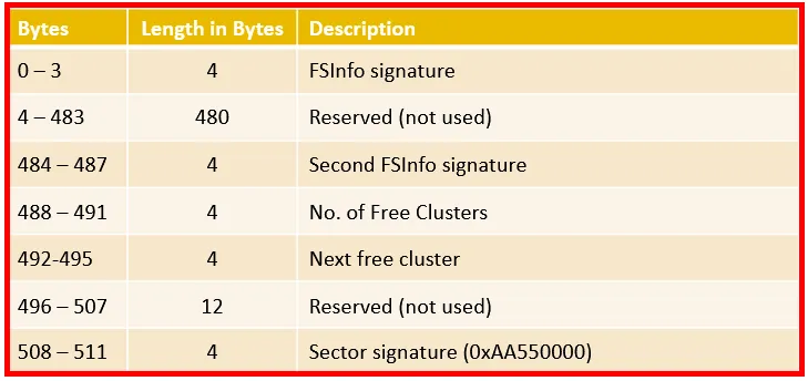
The sections of FSINFO (File System Information) as:
Exploring the FAT32 FSINFO sector:
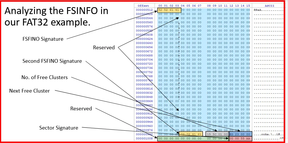
→ FSInfo signature 0x5256141 → RRaA
→ Second Signature 0x7x724161 → rrAa
→ No of free cluster 0x155C0100 → 89109
→ Next free cluster 0xED230000 → 9197
The number of free clusters found was 0x155C0100 is a little endian value, which means we need to translate the value which we get 0x00015C15. And if we translate that value in decimal we get 89109 of free clusters.
But how many free bytes we have? As we study we need to multiply with 512, but it’s invalid. We need to check first, how many sectors per cluster.

So we need first need to multiply the number 89109 with 2, which refers to the number of free sectors. Further we will calculate the total number of bytes, which will be
91,247,616 bytes.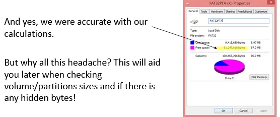
Boot Strap & Reserved Sectors:
We don’t need to know much more about Bootstrap sector, as it has nothing useful. But the sector does end with the end of the sector signature 0x55AA.
And after that, there comes a reserved sector which are usually all zero.
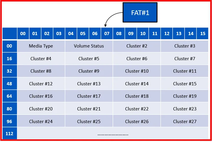
FAT (File Allocation Table) Area:

File systems are divided into clusters and FAT acts as map to these clusters. The length of each entry in map depends on the type of FAT file system used.
We already mentioned that, FAT12 have 12 bits, FAT16 have 16 bits and FAT32 would have 28 bits, as the top 4 bits are reserved.
Let’s explore the the FAT32 system, what each entry actually corresponds:

Since FAT32 only uses 28 bits and not all 32 bits, that’s why the top 4 bits in the table entries are represented with the question mark “?”.
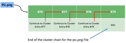
File could have more than one cluster allocated to it. For ex: a file has 4 clusters, it means the first entry for this file will have the number of the next cluster in the chain of clusters.
This is why it acts like a linked-list, the first cluster entry points to the next, and the next to the third, and the third to the fourth. The fourth will be holding an end of cluster or end of chain value.
We read above from boot sector that the first cluster is #2. The main reason is ; the cluster #0 and #1 are both reserved.
Cluster#0: is the first byte that holds the media descriptor and the other three bytes are all ones (1s). So, if we have a hard disk drive, we will find 0xF8FFFFFF.
Cluster#1: is used for dirty volume management. This cluster will store the status of the volume and whether it was mounted and unmounted properly. For eg: If the OS shutdown and didn’t unmount the volume properly, then this cluster will have value indicating for the system at next boot with that volume as in a dirty state. This could help to call the scan or check disk utility to recover the volume and restore its integrity.
As FAT32 uses two FATs (FAT#1 and FAT#2). The high-level view of the entries:
How to locate the FAT within the volume?
Finding FAT#1:
→ GoTo the boot sector
→ Check the value in the “Reserved No. of sectors” section.
→ GoTo that sector value found in (2), which will be FAT#1.
Finding FAT#2:
→ GoTo boot sector
→ Check the value in “Reserved No of sectors” section
→ Check the value in “Sectors per FAT” section.
→ Adding value found in (2) with value found in (3) leads to location of FAT#2
(Another Method):
→ GoTo FAT#1 and add (3) to it.

FAT Data Area:
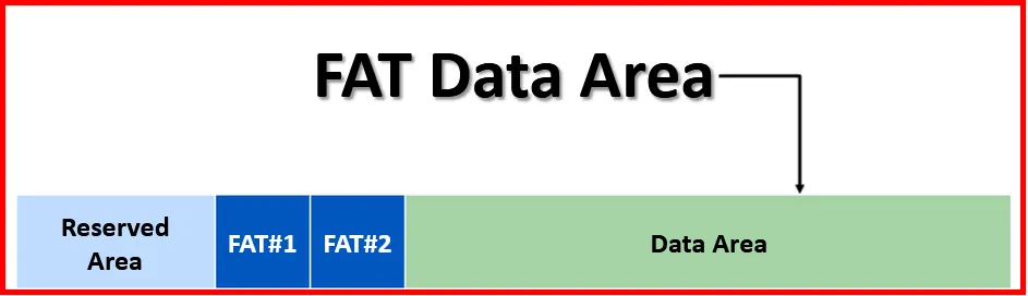
The structure we read, is about the System Area, now the remaining space is called the Data Area.
The FAT DATA area contains the meat of the files stored in the file system, which means this area hold the file’s and directories content.
Here, we found the contents of the files, while directories are special files that hold the file names and metadata of those files. File names use the 8.3 naming convention, where eight characters for the name, and three for the file extension.
Understanding the directories and their metadata, is an important part of any digital forensics investigator, that will be doing forensics on a FAT file system.
FAT12/16 has fixed size section named the Root Directory Area, and that was the limitation on number of files created.
But with FAT32 file system, there is no such limitation and the only limitation is the size of the volume itself. So, as long as there is space there could be directory entries created.
We can reach the location of Data Area by jumping the number of reserved sectors, plus two times the sectors reserved for each FAT.
Data Area Location = Reserved Sectors + FAT#1 + FAT#2
The Root Directory of the file system is located in cluster#2 and, if the volume had label for it, then the first entry in the directory will be for the label of the volume. The label will be maximum 11 characters long. Root directory sometimes called as Root only.
Within FAT32 file system, there are two types of directory entries:
→ Short File Name (SFN)
→ Long File Name (LFN)
Short File Name (SFN) Data Structure:
The structure for SFN Directory entry found in FAT32 file system:
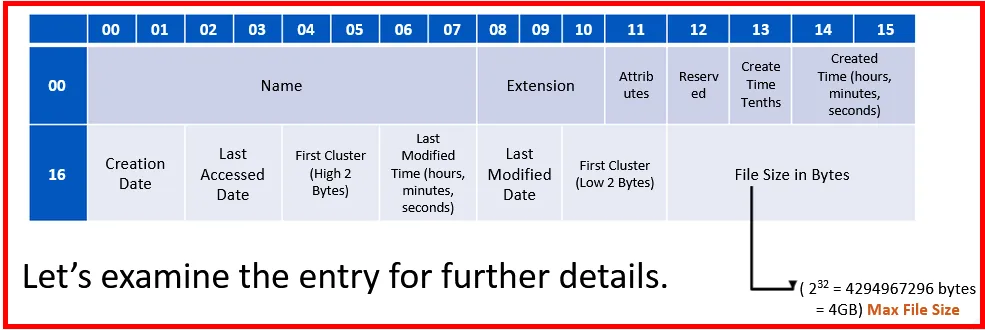
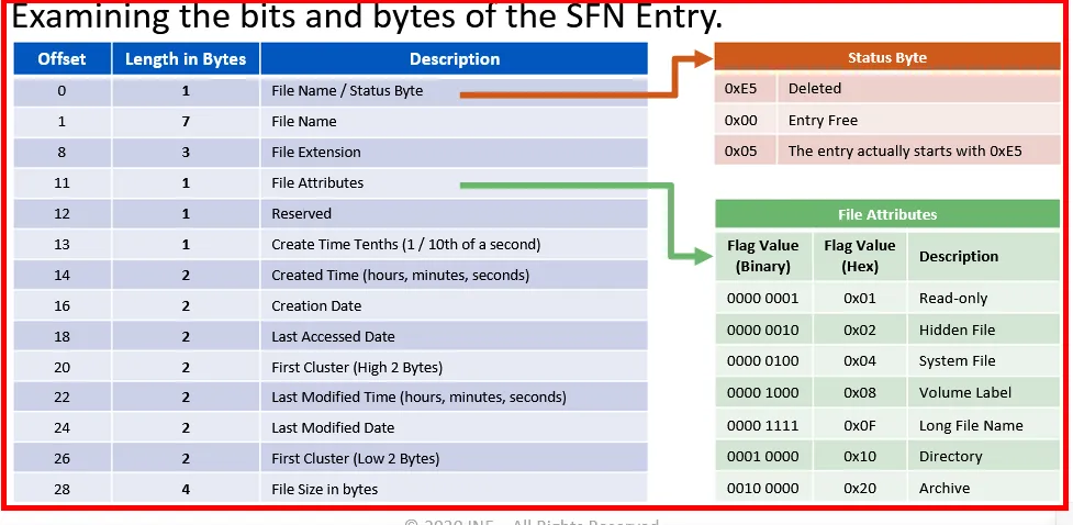
Date Format:
Let’s explore how the Date entries (2-bytes) used to store the date since 1980 up to 2107
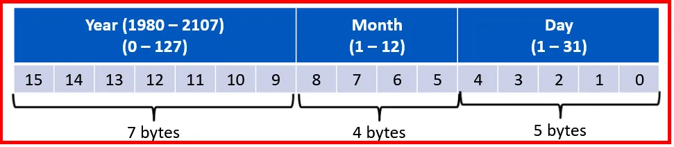 Above written bytes must be changed to bits (Size for Date = 2 bytes = 16 bits in total).
For example, the date September 10, 2017 is represented as:

This means:
→ Year (0100101) = 37 + 1980 = 2017
→ Month (1001) = 9
→ Day (01010)= 10
Time Format:
Also, time format uses 2 bytes (16 bits) for storing time:

For example: time 09:10:55 AM is represented as:
→ Hour (1001) = 9AM
→ Minutes(1010)= 10
→ Seconds (11011) = 55 (Understand 11011 ≠ 55 but still taking that value, why???)
It is because, 55/2 = 27.5 as the system is only using 0-29 seconds, so we are assuming 27 )
We noticed that SFN has naming limitation (above FAT12/16 have naming limitation of Root directory); it can only store files with names; that follow 8.3 naming convention which means the file names could not have a name longer than 8 characters.
To handle that new structure, LFN (Long File Name) structure was introduced with a file name support up-to 255 chars. Also, chars will be in Unicode and not ASCII, so they will use 2 bytes to represent each character.
Whenever there is a file name longer than 8 characters the file system will create a LFN. Note that, there might be more than one LFN entry for a single file, because the LFN structure can only hold 13 characters for the name.
Therefore, the system will create an entry for each 13 character of the file name.
Let’s take an example for a file name: eLearnSecurity DFP course.doc which has 25 chars (including the spaces) as it is allowed within LFN entry. This will create following:
→ SFN Entry
→ LFN Entry #1 holding eLearnSecurit
→ LFN Entry #2 holding y DFP Course.
→ LFN Entry #3 doc
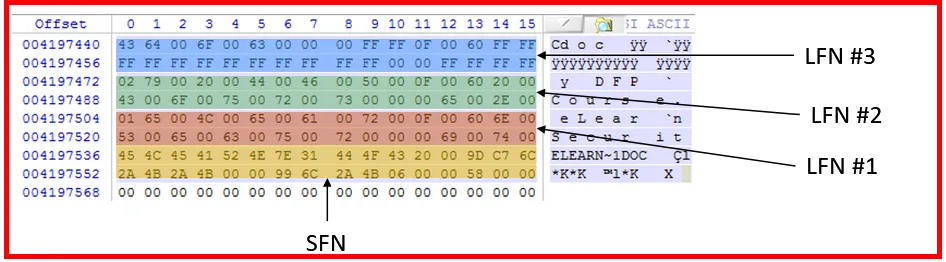
The file naming is stored from upwards as in fig. The last LFN has FF to pad the bytes used for the file name.
Although a LFN is created, it also have SFN entry. The SFN will actually have the first 6 characters of the file name, and the “~” char, then a number.
The LFN entries are synced with the SFN using the checksum value. This value is 1 byte in length, and calculated based on the chars in the SFN.
The number after “~” depends on the number of times a file has the same first 6 characters and is found within the same dir. This will hold upto 4 files, and after that it will use different formula.
For example: Suppose we have another file name eLearnSecurity DFPv2.doc in same directory as our previous file, then the first file created will have a SFN with the name showing ELEARN~1.doc also the new created file will have the name as ELEARN~2.doc
Note: Despite file having upper and lower case chars, there will be a LFN created!
Long File Name (LFN) Data Structure:
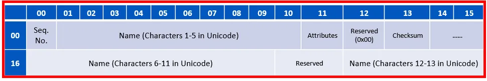
- Seq. No: It is used to track the LFN entry count. The first LFN will have the number 0x01, the second 0x02 and so on. The final sequence number will be 0x40 ORed with the sequence number. So if we have three LFN entries for a file, the final LFN entry will have the 0x43 value as its sequence number.
-
Name: The name is divided into three different locations:
→ Offset 1: Name chars from 1 to to 5
→ Offset 14: Name chars from 6 to 11
→ Offset 28: Name chars from 12 to 13
Note: Offset values are shown in decimal
-
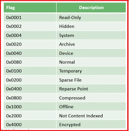
Attributes: Single byte is used to define a set of flags (A)rchive, (D)irectory, (V)olume name, (H)idden file, (S)ystem file, (R)ead-only
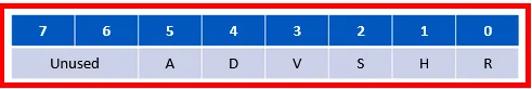
Note: There will be only one entry in volume with V attribute set.
→ Reserved: There are two reserved location, the first is at the offset 12, and the second is at 26. Both the entries are reserved and always holds the value 0x00 and 0x0000 respectively.
→ Checksum: It holds the checksum calculated for the 8.3 name found in the SFN of the file entry. It will be used for synchronization with all LFN entries as mentioned earlier.
→ Subdirectory Structures: They have same structure as we saw before, only that there are two special entries in any subdirectory:
Entry #1 is the **“.”** or Dot. It is actually a pointer to a same directoryEntry #2 is the “..” or Double Dot. It actually points to the parent directory (one-level up in the file system tree).Subdirectories will have their directory attribute set and they will always have a file size of zero, even if the subdirectory has files within it. Also, subdirectories also have date and time sections, just like any other file/directory in the file system.
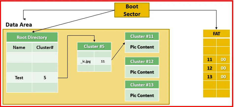
→ File Allocation: We need to know what will happen and how file will allocated a space when it is created. Let’s create a file name Pic.jpg inside a Test directory. The Test directory is directly under the root of the file system. It can be viewed as:

Conclusion:
- From the boot sector we react out to Data Area, FATs, and the Root Directory
- From root directory, we traverse the Test directory which its content is at cluster#5.
- We find the entry for the file Pic.jpg
- The entry says that the file’s first cluster is at cluster #11.
- From FAT we know how to reach to cluster#11, and since the FAT entry for cluster#11 holds the number 12, this means that file has another cluster found at cluster#12.
- We traverse that cluster the same way we did before until we reach to the EOF marker, which tell us the end of the file and no more clusters are allocate for this file.
Deleting a file: Whenever a file is deleted, following will happen:
- The system changes as we mentioned before the first character in the file name, to 0xE5.
- The cluster entries for the file in FAT are all zeroed out.
- The starting cluster in the directory entry is left as it is.
- The contents of the file (in clusters) still exists on the disk (until their clusters are used again).
Let’s explore with example, by deleting the previously created image file Pic.jpg:
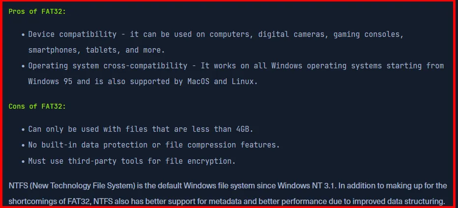
NTFS File System Analysis:
FAT system was a solid solution with few limitations for a long time, but operating systems have evolved and user requirements are totally different today. This lead to new system that could both solve limitations in previously used systems and support new changes required by the Operating System itself or user.

NTFS size limits:

NTFS doesn’t use the same file system separation schemas that structure the disk in a specific way, as we saw in FAT (Boot, FATs, Data), because everything within the NTFS file system is a file.
Hence, there is no need to separate or divide the physical disk structure into different parts (system and data).
As it is mentioned that NTFS based on files and not on dividing the volumes into separate spaces, even though some files will be located in specific places, but they are still files.

NTFS Structure:
NTFS uses a number of different metadata files to implement the file system’s data structures. These files create the whole NTFS file system. The main file is Master File Table (MFT) which is named as $MFT. We can think it as an array of records.
Each file within the NTFS file have either one or more records (entry), even the MFT itself. And yes, it has an entry for itself within the MFT file. The number of records for each file depends on the size of the file.
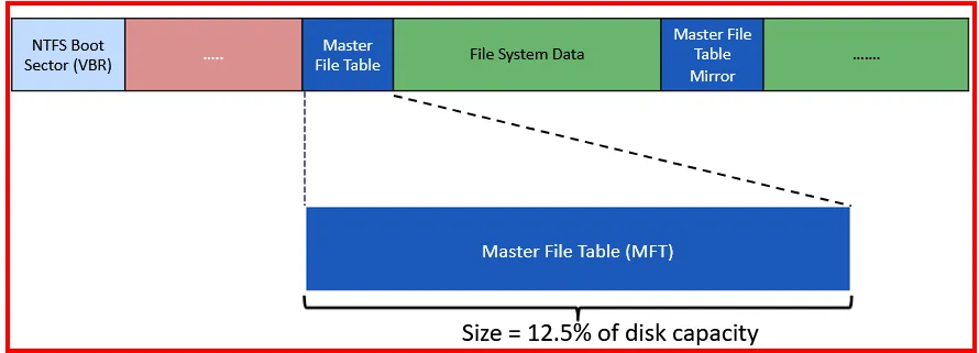
To prevent MFT from being fragmented (file not being contiguous on disk), the NTFS files system reserve some space for the MFT. This space is preserved by default around 12.5% of total disk space. This space is also known as MTF Zone. There are also the other settings such as 25%, 37.5% and 50%.
Note: If the MFT get fragmented, then the MFT Zone gets filled up.
In real scenario, when we formatted a HDD (assume of 100GB) , we find that around 12.5GB are already gone from the disk space. We cannot see them, because they are already reserved for NTFS file system.
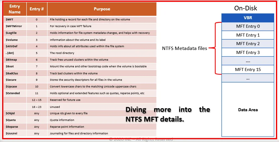
The main NTFS metadata files are:
 MFT reserves the first 15 entries for the file system metadata files.


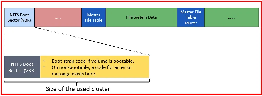
Volume Boot Record (VBR)- $Boot(7):
VBR is found in the $Boot file and record entry number 7. (Look at NTFS file metadata fig above). This file will help the system to locate the MFT within the disk. As we read, $MFT is a file which could be located anywhere on the disk. The VBR helps to locate it.
The size of VBR of NTFS volume depends on the cluster size used for the volume.
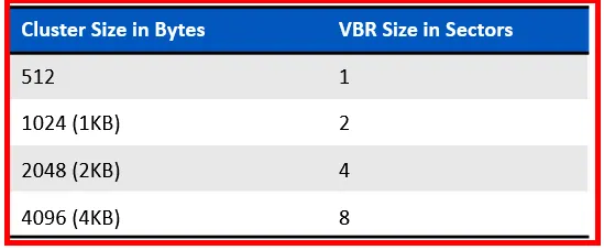
So, if we have cluster size of 4KB, then file system will allocate 8 sectors for VBR.
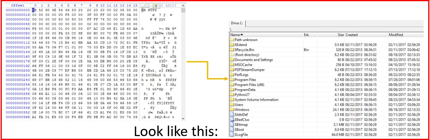
The contents of the $Boot NTFS VBR is shown below as:

The BPB and Extended BPB are further analyzed to give the following!
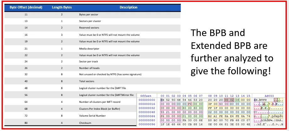
The details of the Volume Boot Record (VBR) and BIOS Parameter Block (BPB):
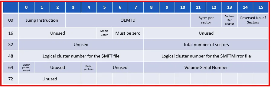
→ Jump Instruction: It holds the jump boot code command:
EB 52 → jmp 00000054
90 → NOP
→ OEM ID: It is a Manufacturer ID, which will be NTFS
→ Number of bytes per sector
→ Number of sector per cluster
→ Reserved number of sectors. This will always be zero because NTFS always has the boot sector at the beginning of the volume.
→ Media descriptor is used to describe the media used. This will usually be 0xF8 on HDD.
→ Total number of sectors has the total number of sectors in the volume
→ Logical Cluster number for the $MFT file: Logical cluster address of the $MFT file
→ Logical Cluster number for the $MFTMirror File: Logical cluster address of the $MFTMirror file.
→ Cluster per MFT Record: Holds the size of each MFT entry
→ Cluster per Index: Holds the size of the index buffer used to allocate directory space.
→ Volume Serial Number: Holds the serial number of the volume.
Now analyze the MFT(MFT):
Further more:
MFT is an index to each file found within the volume. Each MFT record holds a set of records too. We can think of it as an array of records, and each record is another array of records.
The records within the MFT record are called attributes. Each attribute is used to store a different type of information.

NTFS file system uses a different number of attributes, and each attribute is used to store some different type of information. Any single MFT entry/record will have different number of attributes. This depends upon the nature of the entry itself.
Let’s first explore the NTFS file system attributes:

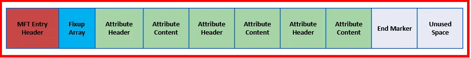
NTFS MFT Entry:

Now let’s analyze the contents of entry (record) which is built-up using a header, a number of variable length attributes and an end marker. The marker is usually 0xFFFFFFFF.
→ Entry Signature: Every file in NTFS file system has at least a single MFT entry (or record) which is around 48 bytes.
Each entry starts with the signature FILE or in Hex (0x46494C45). If the entry is usable, then it is marked with BAAD.
→ The two bytes at offset 4 are used for the fixup array.
→ The next two bytes are for the entries in the fixup array
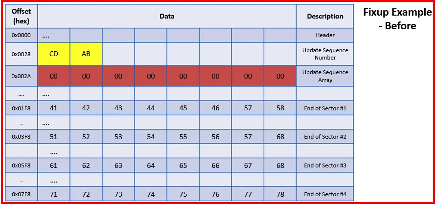
Fixup Arrays:
As clusters are formed from number of sectors, and sectors could be corrupted. NTFS file system uses Fixup Array technique to ensure the sector is not corrupted and the data’s integrity is maintained. In other words, It is used to detect if any errors are found in cluster.
Each sector will have Fixup Array which is stored in an Update Sequence Array.
How is it Used?
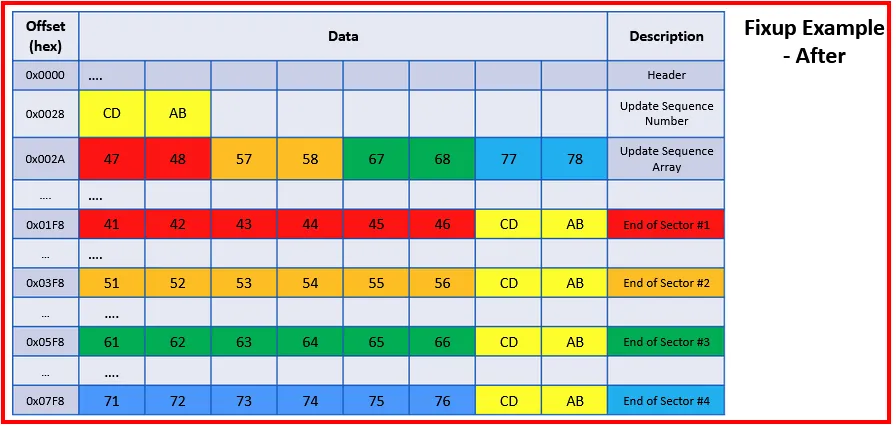
The header of each entry contains an Update Sequence Number and a Buffer. The last two bytes of each sector of entry are copied into the buffer (Update Sequence Array) and two bytes are replaced with the Update Sequence Number.
When an entry is read, the Update Sequence Number is read from the header and compared with the last two bytes of each sector. If a match is found, then it will copy the bytes in the buffer back to their original location.
Fixup - After:
Fixup arrays are not only used in File entries of $MFT, they are also used in:
INDX entries in directories and other indexes.
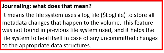
RCRD and RSTR entries in the $LogFile
→ The next eight bytes are used for the $LogFile Sequence Number. This is changed every time the record is modified.
→ Sequence Number: holds the number of time the MFT entry has been reused. It will be incremented with one every time the entry is used and released.
→ Hard Link Count: holds the number of hard links i.e the number of directory entries referencing this entry. This is used in base entries only.
→ Offset to the first Attribute: Holds the position value of the first attribute of the entry.
→ Flags: Holds any of the following status information values:
- 0x01 → Entry is in use
- 0x02 → Entry is for a directory
- 0x03 → Unknown
- 0x04 → Unknown → `Real size of the MFT entry (record)`: Holds the actual size of the MFT entry. The size will be padded to an 8 byte boundary.
→ Allocated size of the MFT entry (record): Holds the size of each MFT entry within MFT. It is usually 1024 bytes.
→ File reference to the base MFT entry (record): It will be zero when entry is for the base MFT entry. When it is not zero, it means it is holding the value referencing the Base MFT Entry. The Base MFT entry contains all the information about the extension entry, which is stored in ATTRIBUTE_LIST attribute.
- Value (zero) : Base entry
- Value (non-zero): Reference to base entry
→ Next Attribute ID: Holds the value that is assigned to the next Attribute added to this MFT entry. The value is incremented each time it is used and every time the MFT entry is reused this ID is set back to zero. The first instance number is always zero.
→ Align to 4 bytes boundary & number of this MFT Entry (Record): The align and number of this MFT Entry are both values used in old versions of the Windows Operating System (Windows XP).

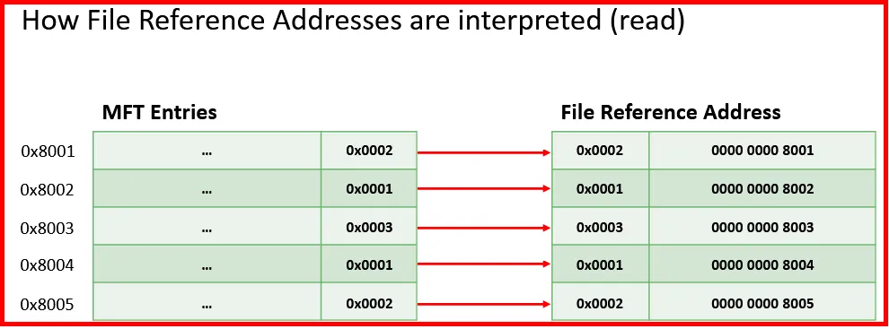
MFT File Reference Number:
Each MFT has a Sequential Address which start from zero (as $MFT itself has the entry number zero). Each MFT addresses uses a 6 byte number (48 bits) and is preceded with 2 bytes for MFT Sequence Number. The combination of both the MFT entry number and MFT sequence number is called MFT Reference Number.

This address is used whenever a structure needs to refer to a record in the MFT.

Note: The MFT sequence number will be incremented each time an MFT file entry is reused. Even though the MFT would create a new entry for a new file, the entries that no longer belong to a file, (may it was deleted), will be reused. When this happens the sequence number gets incremented, For example: from 1 to 2.
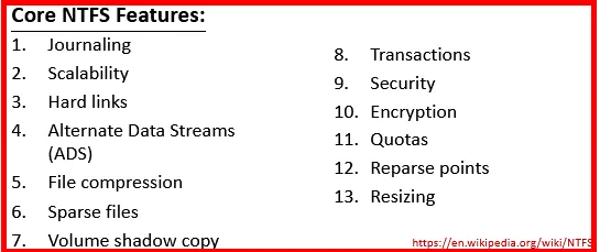
NTFS Attributes:
The attributes are used to store different information(name, timestamps, content etc.) and most of them are found within MFT entry itself. The general layout:
Each attribute has a header and content. Attributes could be either resident or non-resident.
→ Resident attributes have header and it content come directly after it. Examples are: $STANDARD_INFORMATION and $FILENAME.
→ Non-Resident attributes are stored in separate clusters of the disk, which means their cluster is not within the MFT entry itself. Example is: $DATA attribute. An attribute named $ATTRIBUTE_LIST will be used for tracking.
If a file size is less than 700 bytes then the attribute is resident, if greater than 700 bytes then it’s non-resident.
Despite of being resident or non-resident, both will have 16 byte common attribute header.

→ The first four bytes (Attribute type identifier) holds the attribute type identifier.
→ Then next four bytes (Length of attribute) have the total length of the attribute. This value includes the length of header.
→ Flag is used to check whether the attribute is resident or not. A non resident flag will hold the value of 0x01
→ The length of the attribute name uses 1 byte, and the offset to the name’s location or position uses 2 bytes.
→ For attribute flag, we have three types: - 0x0001 → Compressed - 0x4001 → Encrypted - 0x8001 → Sparse
→ Every attribute have a unique identifier that is used to distinguished between all attributes that could be found within the MFT entry.
The structure of resident attribute header is:
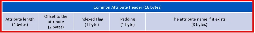
→ Attribute length describes the size of the attribute and the offset holds where this attribute is located.
→ Padding holds a 0x00 value, and used for padding only.
→ If the attribute has a name, then it will be in the last 8 bytes.
A non-resident attribute header will have:

Virtual Cluster Number (VCN):
It describes the sequence number of cluster associated with a file or attributes regardless of where it is in the file system.
Logical Cluster Number (LCN):
This is a cluster number that is relative to the first cluster after the VBR of the volume.
Starting and ending VCNs are used when multiple MFT entries are needed to describe a single attribute. The offset (position) of the runlist (it is a sequence of cluster runs that contain the data for the file) is relative to the start of the attribute.
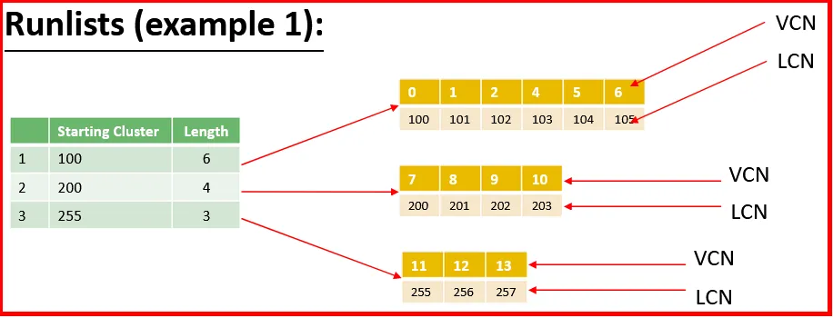

In this example, we can see that the clusters are not in ascending order. This can happen when a space for a file got unallocated in previous location on the volume.
Standard Information Attribute ($SIA) - [0x10]:
This attributes stores the standard file information such as size, security, timestamps, logging info etc. It has minimum size of 48 bytes and maximum size of 72 bytes. It will always be a resident attribute, which means it will always be stored within the MFT entry itself. It uses an attribute ID of 0x10.
One important thing to remember is: Each attribute has an attribute header. The header is used to store the information about the attribute:
- Type
- Size
- Name (Optional)
- Resident or Non-resident
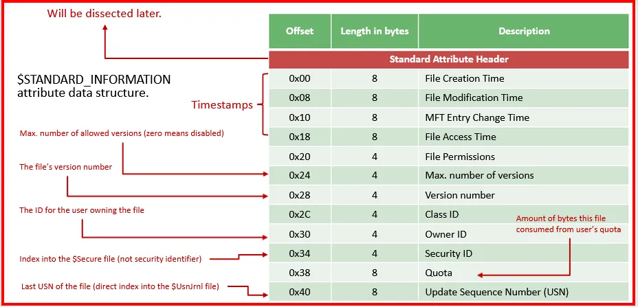
File permissions are analyzed into the following: