Notiz
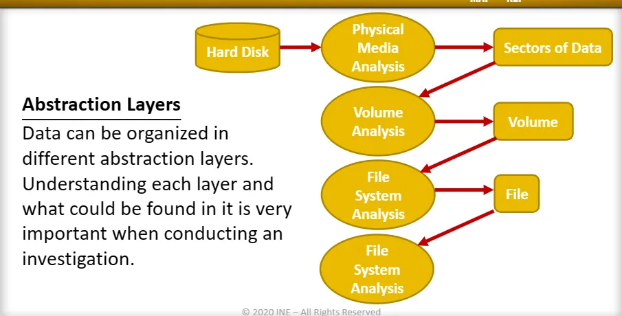
Disk Drives

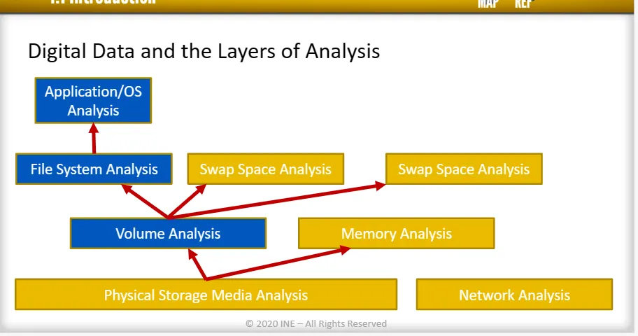
Each layer of data requires a different type of analysis. Especially, disks and file systems analysis is divided into four layers:
→ Physical media
→ Volume
→ File System
→ Application and OS
Hard Disk Drives:
Hard disk drive is a storage unit that uses magnetic storage to store and retrieve digital data.
How Magnetic storage store data?
The hard drive contains spinning platter with a thin magnetic coating. A “head” moves over the platter, writing 0’sa and 1’s as tiny areas of magnetic North or South on the platter. To read the data back, the head goes to the same spot, notices the North and South spots flying by, and so deduces the stored 0’s and 1’s.
HDD Characteristics:
There are many components **of HDD but the mainly interested **four are:
→ Platter - Similar to plate, it is the one that store the digital data.
→ Spindle - Used to mount (Carry) platters and spin them.
→ Head - This part is concerned with reading from or writing on the platter.
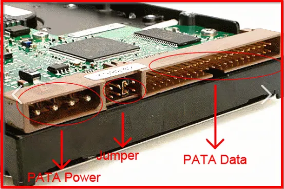
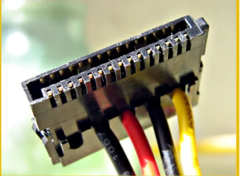
→ IDE Connector - It is the interface connector used to connect the HDD to the main board (its type is IDE)
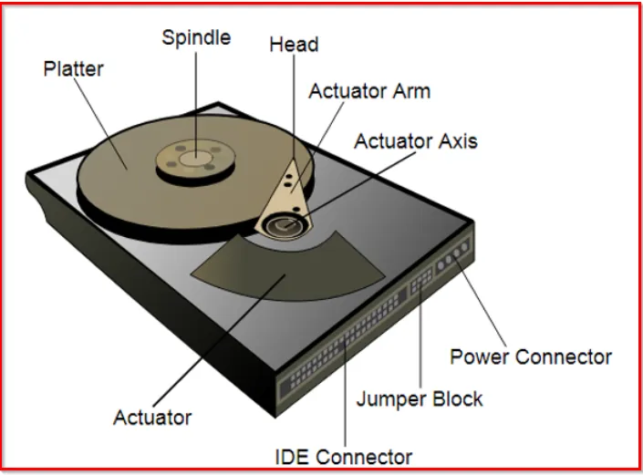
Other characteristics :
→ Actuator: A mechanical arm that moves the head for reading and writing in an axis direction.
→ Power Connector: Connecting power source to the drive.
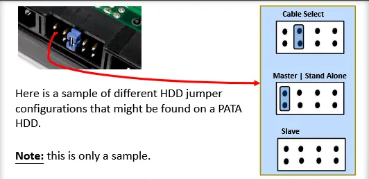
→ Jumper Block: Small conductors used to configure the hard disk drive priority connected to the same cable.
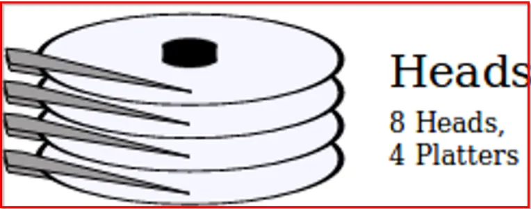
Modern HDD are constructed from a number of Platters, not just a one. And all the platters are placed in single spindle.
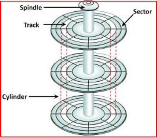
Cylinder: From figure, if we select a track number 1 on first platter, and track number 1 on second platter, and so on, this will form what we call a cylinder. So, the cylinder is the respective circular tracks aligned (to get into line) through the stack of platters.
That means, the number of cylinders is equal to the number of tracks available on the disks.
Each platter has two heads, one from each side.
Each platter is divided into the number of tracks, just like a circular path. And each tracks is divided into number of sectors. As in fig:
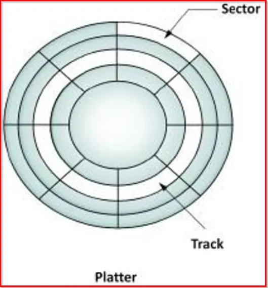
[Note: On an IBM-PC Compatible, there is 63 sectors , as six bits used for no of sectors]
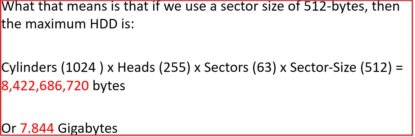
Most HDD have a logical sector size of 512-bytes except a new industry type of disks with Advanced Format (AF) which are moving to 4096-bytes sector size.
[Note: The sector size is the smallest amount of data read or written by HDDs]
In order to calculate the total disk capacity, we need to have the info of:
- Number of Cylinders (which is equal to number of Tracks)
- Number of Heads
- Number of Sectors per Tracks
- Sector Size
Disk Capacity = (Cylinders) x (Heads) x (Sectors) x (Sector Size)
To access a specific sector, there are two physical addressing methods:
→ Cylinder, Head, Sector (CHS)
→ Logical Block Addressing (LBA)
Using CHS Addressing:
This is the old method, where the addressing is based on the physical geometry of the Cylinder, Head and Sector (CHS). Example: If you want to access the first sector on the disk, the address will be (0,0,1) , second will be (0,0,2) and so on. It means:
First Cylinder → 0
First Head → 0
First Sector → 1
[Note: For CHS addressing method, the sector always starts with 1 not 0]
Another important aspect: The head number is used to specify the side of the plate that you want to access. Example: If we say head 1, it means it will be accessing the bottom side of the plate. That means head 0 → top side of the plate. (In above example, head is top side as head = 0)
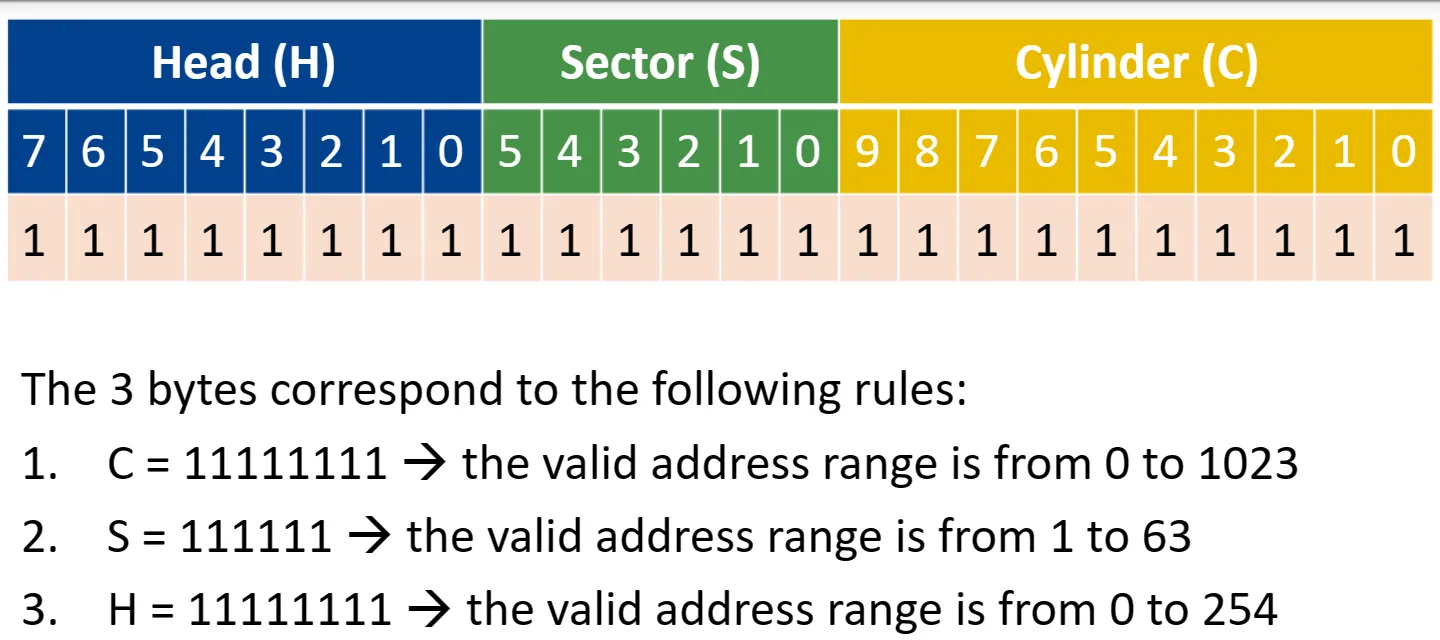
In CHS, three bytes are used for addressing and are divided as:
- Cylinders (C) uses 10 bits
- Heads (H) uses 8 bits
- Sectors (S) uses 6 bits
[ From above fig: understand, Sector always starts with 1.]
Using LBA Addressing:
LBA Addressing uses a single number to address each sector. It means: the CHS address (0,0,1) corresponds to LBA address 0, and CHS address (0,0,2) corresponds to LBA address 2, and so on.
[Due to backward limitation on LBA, some file systems still need to be able to address sectors based on CHS, it means a conversion equation is needed]
The CHS scheme exposed the physical details of the storage device to the software of operating system. In CHS, blocks were addressed by means of the tuple which defined the cylinder, head and sector at which they appeared on the hard disk. CHS did not map well to devices other than hard disks (such as tapes and networked storage) and was generally not used for them. CHS was used in early MFM (Modified Frequency Modulation [a run-length limited (RLL) line code used to encode data on most floppy disks and most HDDs]) and RLL drives and bot it and its successor, extended cylinder-head-sector (ECHS), were used in the first ATA drives.
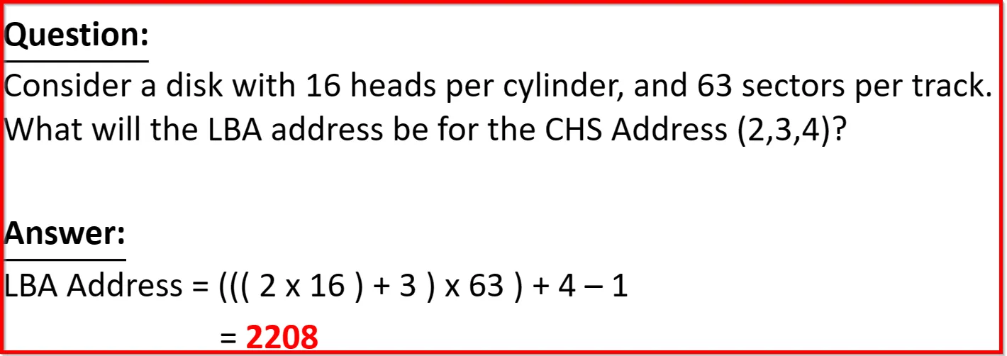
To convert from CHS to LBA address, use the following equation:
LBA Address = (((Cylinder x HeadsPerCylinder) + Head) x SectorsPerTrack) + Sector - 1
Modern HDD uses LBA addressing method (due to lack of limitations like CHS) and is not related to the geometry of the HDD. Every block will have a unique number, and that number will be referenced whenever that block is needed either for reading or writing.
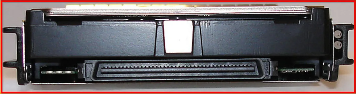
Interfaces:
Types:
-
ATA: Originally called the Advanced Technology Attachment (ATA) which was used as an interface with storage device (HDD). Currently, referred to as Parallel ATA (PATA).
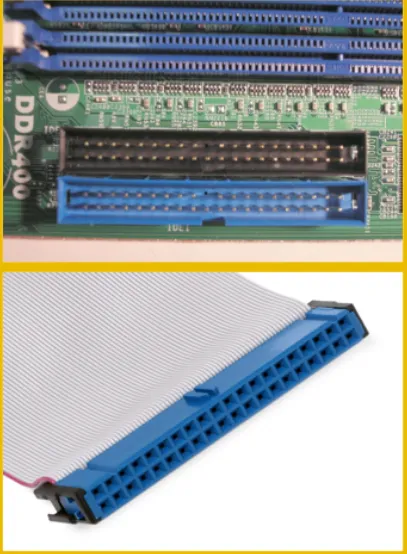
This was most commonly used interface, even though it isn’t the market dominator today but still we may encounter them during the investigation.
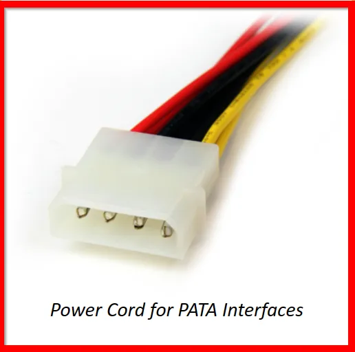
PATA interface were not flexible and required jumpers to configured properly , especially when more than one drive was attached to the interface. This is the main reason, Serial ATA (SATA) is used today instead of a Parallel ATA (PATA).
Serial ATA (SATA) interfaces are much more flexible and do not require any special configuration or a jumper!
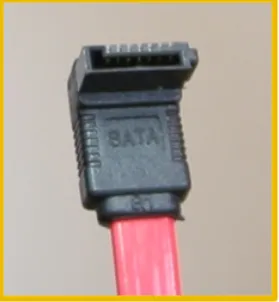
Side by side comparison for two different connectors:
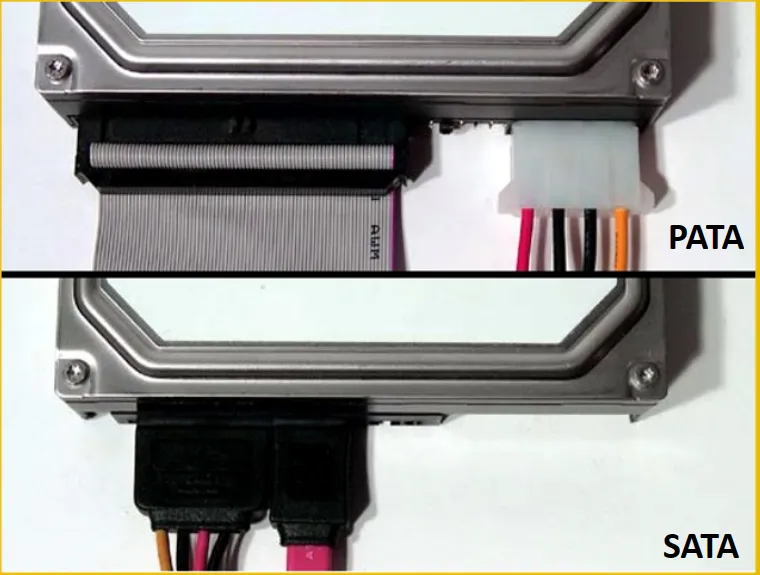
SATA only transfer a single bit at a time as compared to PATA, which can transfers 16 bits.
A drive connected to SATA interface is directly connected, whereas a device on PATA interface could be chained, so special configurations might be needed.
SATA has several advantages over PATA, like: smaller cables and connectors, higher bandwidth (increased transfer rate), and are much more reliable.
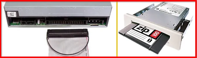
CD-ROMs and Zip Drives use the same interface but uses a different protocol named AT Attachment Packet Interface (ATAPI). This allows both the PATA and SATA to attach devices to such interfaces.
Another interface we learn within this course is the Small Computer System Interface (SCSI), pronounced “scuzzy”. This type of interface is rarely found within the personal computers, as they are commonly found within the servers.
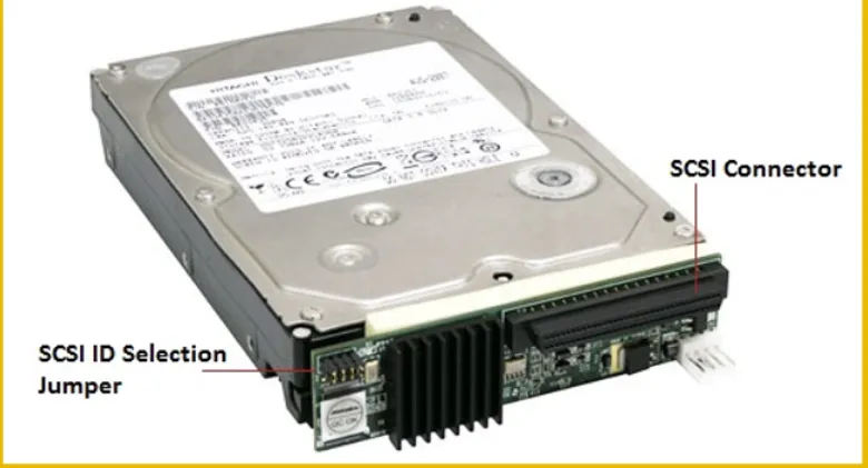
If we encounter such type of interface, make sure you check the manuals before being used as SCSI has wide range of minor types.
BIOS (Basic Input/Output System)
It’s the first system software that interact after a start or power button is clicked within PC. It provides the computer with an interface to basically interact with the hardware found.
BIOS is stored in the main board of the computer and uses EEPROM (Electrically Erasable Programmable Read Only Memory) and CMOS (Complementary Metal-Oxide Semiconductor) to store its configuration.
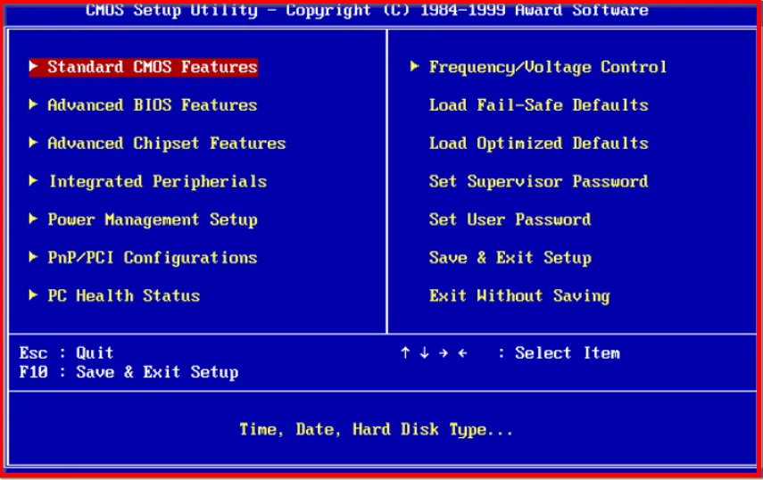
After the BIOS initializes the hardware required to boot the system, it transfers control to the Operating system to take over.
Booting OS: To start the operating system, BIOS immediately jump to sector zero (top part) of the disk, which holds the MBR. From the MBR it locates the partition marked as bootable, and executes the machine code as:→ whether to jump to that partition or load the operating system (in the past).
SSD (Solid State Drive):
These type of drives are really complex and pose challenges for an investigator! So it must be handled carefully, or you might find your evidence inadmissible.
This type of drive has no any mechanical parts spinning around, or arms moving in and out, but rely on electronic chips to store data.
Most common type of SSD use MLC NAND-based (Multi-Level Cell) flash memory ; so it retains data when power is lost.
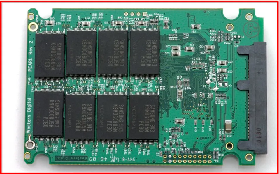
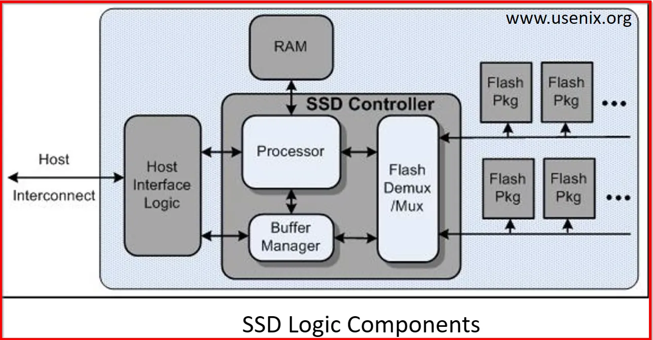
Due to NAND flash memory, they are able to retain the data even when no constant power supply is available. NAND flash components come in different densities per chip. The most common are from 16GB to 64GB per chip. Also, internally, NAND Flash use structures called Pages and Blocks.
A page is the smallest readable or writable unit on a SSD. The standard used size of a page today is 4KB , on HDD the smallest unit was a sector and is usually 512 Byte.
The group of pages within SSDs called block.
While checking the disk specification within SSD, we will most commonly find that it has 128 pages in a single block, a total of 512KB. [As 1 page = 4KB then 128 pages = 128 x 4 = 512 KB]
A block is the smallest structure that can be erased in NAND based flash drive. Although, you can read and write to a page, you can only erase a block. It means we can erase only 128 pages at a time.
The group of blocks within SSDs are called planes. Within a single plane, SSD has 128 blocks.
Volumes & Partitions:
Disk are usually logically divided into number of sections called Partitions.
Volume is a collection of sectors that don’t have to be physically consequential (contiguous) but they are logically consequential.
While Partition is a collection of consequential number of sectors.
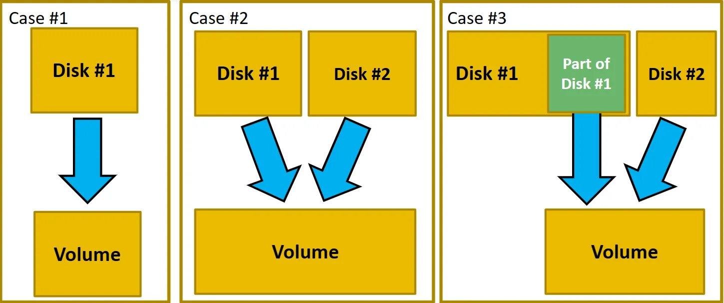
Lets understand the above Figure:
-
Case 1:
→ We have single disk with no partitions, which means we have a single volume. The whole disk is a volume.
-
Case 2:
→ We have two separate disk drive and are combined to create a one big drive. The bigger drive is now a volume.
-
Case 3:
→ We have two disk drive where only a partition is used from disk 1 and whole disk is used from disk 2. Further both are combined to create a new big drive ; a new volume.
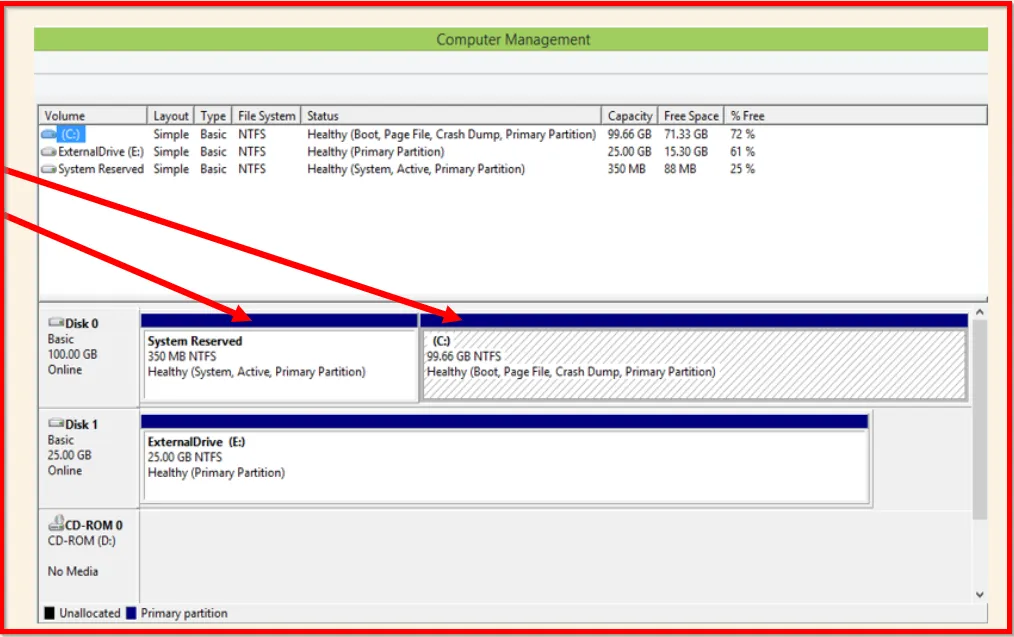 Fig shows how Windows uses at least two partitions. One hidden for the reserved system files and other for the system itself.
Disk Partitioning
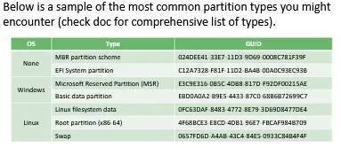
The most common partition table schemas are:
- IBM DOS, knows for MBR (Master Boot Record)
- GUID partition Table (GPT)
Master Boot Record (MBR):
MBR holds up a whole sector and is located at the first sector of the hard disk drive. (LBA 0, or CHS (0,0,1)).
The MBR structure holds three important information:
- Boot Code
- Partition Table
- Signature
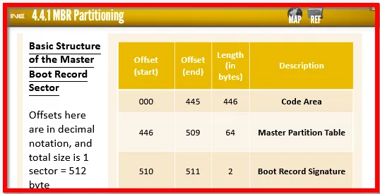
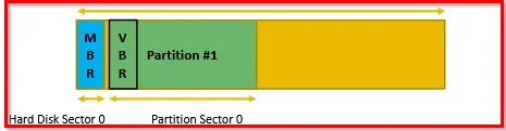
The boot code is 446 bytes and it was previously used to start the operating system. But modern operating system couldn’t fit in 446 bytes so the Boot Section in MBR nowadays used to locate active partition and call that partition: that is marked as Bootable and call which is known as Volume Boot Record (VBR).
The only difference between VBR and MBR, is that the latter is found at the exact beginning of the whole HDD, while the VBR is located at the start of the partition.
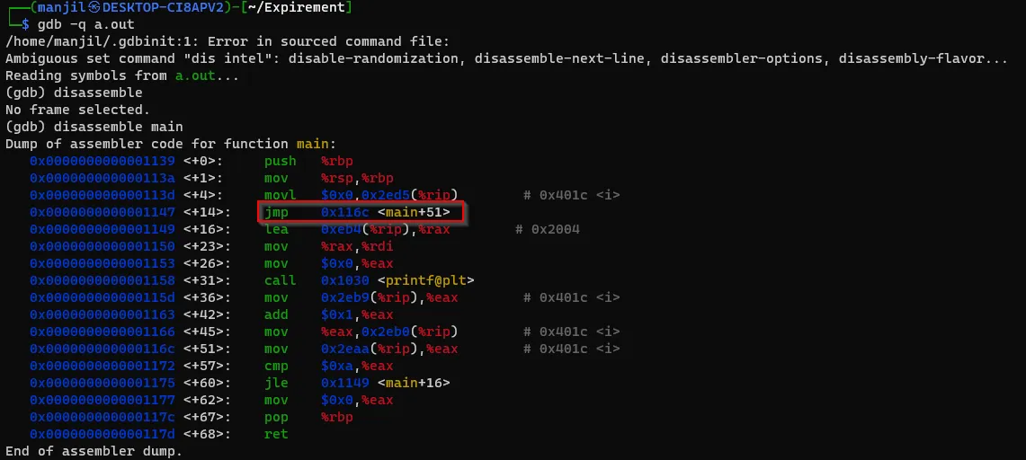
While we analyze the Assemble Language, the data found in the code area section is actually assemble jump instruction and other parameters are used to locate the OS or active partition and load it.
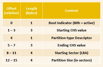
Let’s analyze the 64-byte Partition Table section that is found in MBR.
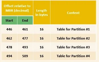
We have four entries each of 16-bytes.
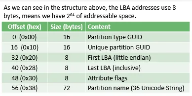
While analyzing the details for the partition entry, the structure of 16-byte Partition Table Entry:
The IBM-PC using an MBR partitioning standard could only be for 4 primary partitions.
A machine using an MBR and needs more than 4 partitions called an extended partition.
Extended partitions are created by transforming a primary partition. With this done, we will have another volume which could be partitioned again! This could not be used for storage but yet need to have a partition within it.
Partition created within an extended partition are called Logical Partitions.
Number of logical partitions that could be created within an extended partition depend on the system and version being used.
It’s better to consult system’s documentation if such case is encountered. And better to be careful while analyzing such disks.
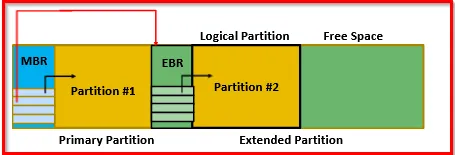
The content of MBR must be carefully interpret and parsed. An entry in the MBR will be pointing to Extended Boot Record (EBR) despite having resources that just call it another MBR.
The EBR will have the same structure as the MBR, but only have two partitions. There could be anything inside the extended partitions unless we go there and parse it.
The first entry is for partition #1, and the second entry could be pointing to another EBR.
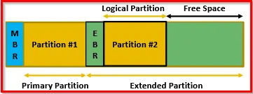
Example of disk with two partitions. One primary partition and an extended partition with logical partition.
Using DiskEditor tool, we can analyze all the physical devices (drives) we have:
Jumper:
It is found in PATA HDDs. It is usually a simple electrical circuit closer. It closes the electrical circuit in order to achieve some specific configuration.
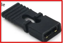
Since, IDE cable could be connected to more than one drive at the same time, this jumper is used in order to help the system to identify whether the drive is primary or secondary.
GPT and The New Booting Technology
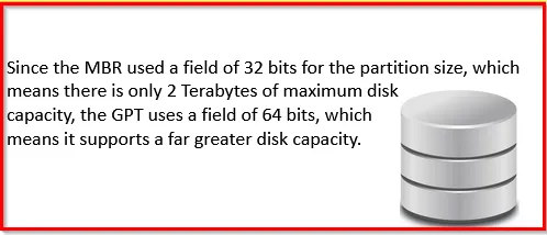
MBR has number of limitations:
- MBR could be only used to create 4 primary partitions
- HDD couldn’t exceed 2TB capacity limit (it is 2^32)
- Most of the hardware vendor started using UEFI instead of BIOS
To overcome above limitations , Unified Extensible Firmware Interface (UEFI) and GUID Partition Table (GPT) comes in. GUID is the abbreviation for Globally Unique Identification.
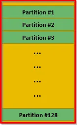
Also, while MBR scheme supports 4 primary partitions, GPT supports up-to 128, and no need for extended partition. As extended partition is not supported within GPT scheme.
Another feature of GPT is, partition labeling. That means, each disk or partition could have a unique label.
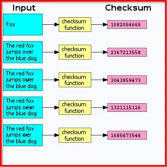
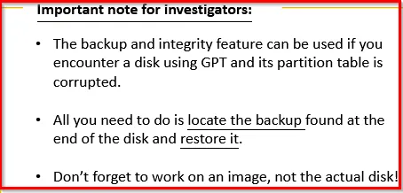
GPT scheme provides both backup and integrity checking. Checksums of the header and partition table is maintained at the end of the disk (last sectors).
(Checksum is a small-sized block of data derived from another block of digital data for the purpose of detecting errors that may have been introduced during its transmission or storage)
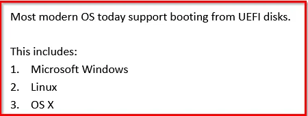
Modern OS support mounting and accessing GPT based disk drives without the need of UEFI. This allows access to data on disks only. If a user want to boot their OS from GPT based disk then they must use the UEFI system for booting. This means, you might find a UEFI partition used for that purpose.
The UEFI framework connects the OS with the system firmware and it acts like a bridge between them. So, during the booting of the system it is capable of locating the UEFI system partition and begin the bootstrap process.
[Note: Bootstrap process is the process where the system chooses its next destination]
After that, the UEFI system is capable of locating the OS partition and execute the necessary files to initialize and load the OS.
GPT Layout:
The layout of GPT based disk is totally different as compared to MBR, and have the following structure as:
- Protective MBR
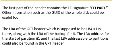
- GPT Header
- Partition Table
- Partitions
- Backup of both GPT Header and Partition Table
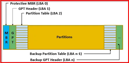
For flexibility reason, GPT based disks separates the partition entries from the first sector on disk.
- The first section of the GPT based disk is the Protective MBR. This section helps the tools that don’t support or recognize a GPT based disk to at least not corrupt it or try to modify the disk. It will help tools to understand that there is a partition available but the tool doesn’t know what it is. Protective MBR uses a partition type 0xEE and defines a pointer to span either the entire disk if the disk is maximum 2TB, or span at most 2TB disk space, based on the MBR scheme limitation.
-
The next section is GPT Header, which is placed in separate section for much more flexibility and more additional feature which is lacked in MBR based disks.
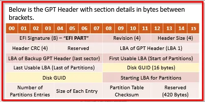
When the disk is using 512 bytes sector size, then the last reserved sector (420) will be filled with zeros. But if the disk is using different sector size, such as 4096 bytes then there will be more than 420 bytes of zeros.
To work with data at this layer we will always encounter data structures and must be prepared to interpret and understand them.
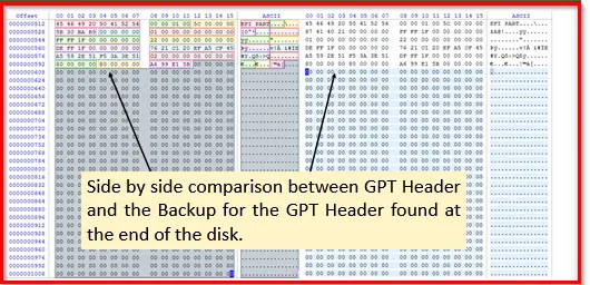
GPT based disks use a backup copy of the GPT header and is found at the end of the disk.
A side by side comparison is:
GUID is “Global Unique Identifier”. GUID is mostly used when you will be defining an ID that mus be different from an ID that someone else (outside of your control) will be defining. Let’s take an example of ActiveX controls (small program used to share information between applications). Anyone can create an ActiveX, and not know with what other controls someone will be using them and there’s nothing to stop everyone from giving their controls the same name. GUID keep them distinct.
Understand: Acquiring GPT based is same as of acquiring MBR based disk. These schemes are only a way of defining how the disk is partitioned and structured logically.
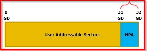
Hidden Protected Area (HPA):
Hard disks can be manufactured or configured to have HPA.
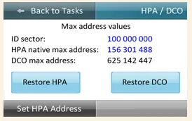
HPA is an area of the disk that is invisible to the operating system. It means vendors could store data that cannot be erased with basic operating system formatting of the drive.
This small storage area is used for different reasons ranging from helping systems boot, diagnostic utilities, basic OS from system install and recovery, up to security services for tracking stolen devices.
Also, hackers could use it to store rootkits and or hide their illegal data (child pornography, etc.)!
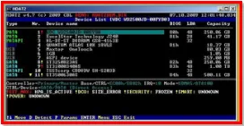
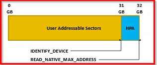
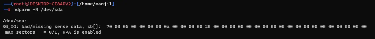
To detect HPA existence, we can use ATA commands and compare the results.
Tools used to detect the existence of HPA on HDD are:
- CLI tools such as the Linux hdparm command
- The Sleuth Kit (TSK) by Brian Carrier
- The ATATool by Data Synergy
- Checking kernel message with dmesg
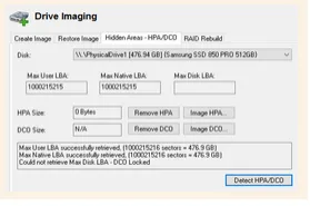
Advanced tools :
- EnCase
- Forensic Toolkit by Access Data
- Atola Bandura from Atola Technology
- OSForensics by PassMark Software
Tools:
Disk Editors:
This tool will help to analyze disk at the logical level. It will allow us to analyze the bits and bytes of the disk, volumes and partitions.
We will be using them to analyze the partition table of a disk and to understand their layout, plus other file system related stuff. Also discuss about bytes and hexadecimal.
Recommended to use Active@ Disk or X-Way’s WinHex. Though HxD is good option too (it hasn’t been updated for while)
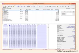
Fig: WinHex
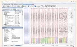
Fig: Active@Disk
Features of Active@Disk
- Navigation using offsets, sectors and even file system entries
- Bookmarks and Colored Tooltips
- Templates to compare with
- Searching and Unicode Support
Also, can be integrated with recovery tools: Active@ Undelete
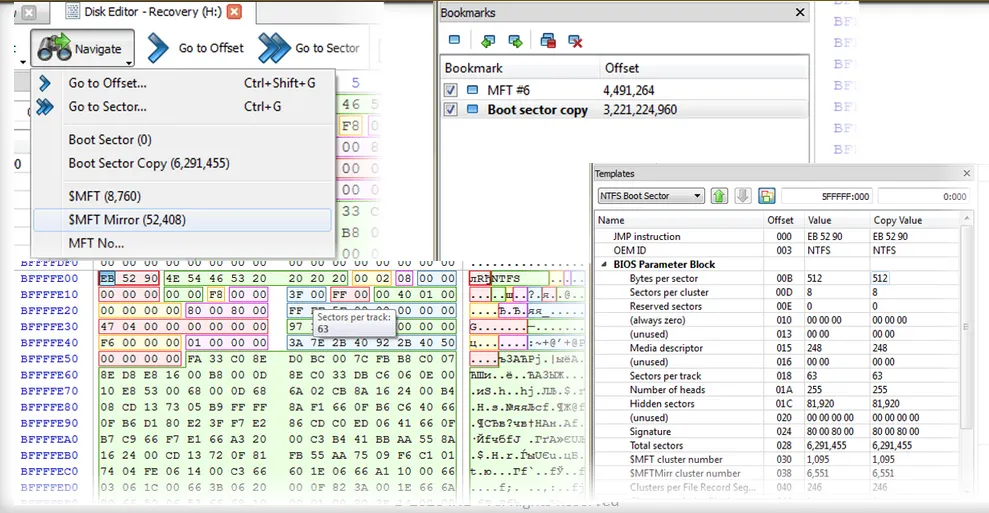
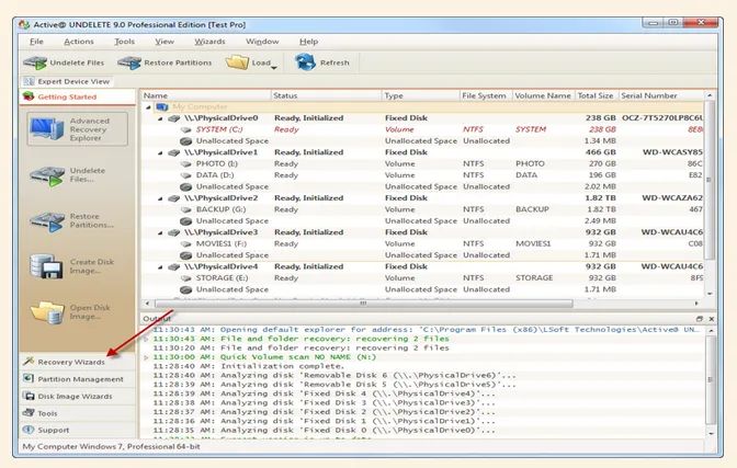
Fig: Active@Disk with Active@Undelete